Flexible data replication mechanism

a data replication and flexible technology, applied in the field of data storage system error recovery, can solve the problems of large time and expense, many of these operations required significant manual intervention, and the effect of replicating provided little benefit until failur

Inactive Publication Date: 2005-09-20
HEWLETT-PACKARD ENTERPRISE DEV LP
View PDF26 Cites 169 Cited by
  • Summary
  • Abstract
  • Description
  • Claims
  • Application Information

AI Technical Summary

Problems solved by technology

In such architecture, the replica provided little benefit until failure.
In the past, managing a data replication system required significant time and expense.
This time and expense was often related to tasks involved in setting up and configuring data replication on a SAN.
Many of these operations required significant manual intervention, as prior data replication architectures were difficult to automate.
This complexity made it difficult if not impossible to expand the size of a replicated volume of storage, as the changes on one site needed to be precisely replicated to the other site.
While effective, the HSG80 architecture defined relatively constrained roles for the components, which resulted in inflexibility.
Failure of either port would be, in effect, a failure of the entire controller and force migration of storage managed by the failed controller to the redundant controller.
Similarly, failure of a communication link or fabric coupled to one port or the other would render the controller unable to perform its tasks and force migration to the redundant controller.
Such migration was disruptive and typically required manual intervention and time in which data was unavailable.
Such architectures were unidirectional in that the backup site was not available for operational data transactions until the failure of the primary site.
Such rigidly assigned roles limited the ability to share storage resources across multiple topologically distributed hosts.
Moreover, configuration of such systems was complex as it was necessary to access and program storage controllers at both the primary and secondary sites specifically for their designated roles.
This complexity made it impractical to expand data replication to more than two sites.
This lack of flexible configuration results in constraints imposed on the configuration and functionality of DRM implementations.
Further, the replicas were not allowed to vary from the original in any material respect.
Prior systems could not readily support dynamic changes in the size of storage volumes.
The lack of flexible configuration constrains the number of replicas that can be effectively created.
While a single replica is beneficial for disaster tolerance, it is of limited benefit to improving performance benefits from migrating or distributing data to locations closer to where the data is used.

Method used


Image

  • Flexible data replication mechanism
  • Flexible data replication mechanism
  • Flexible data replication mechanism

Examples


Embodiment Construction

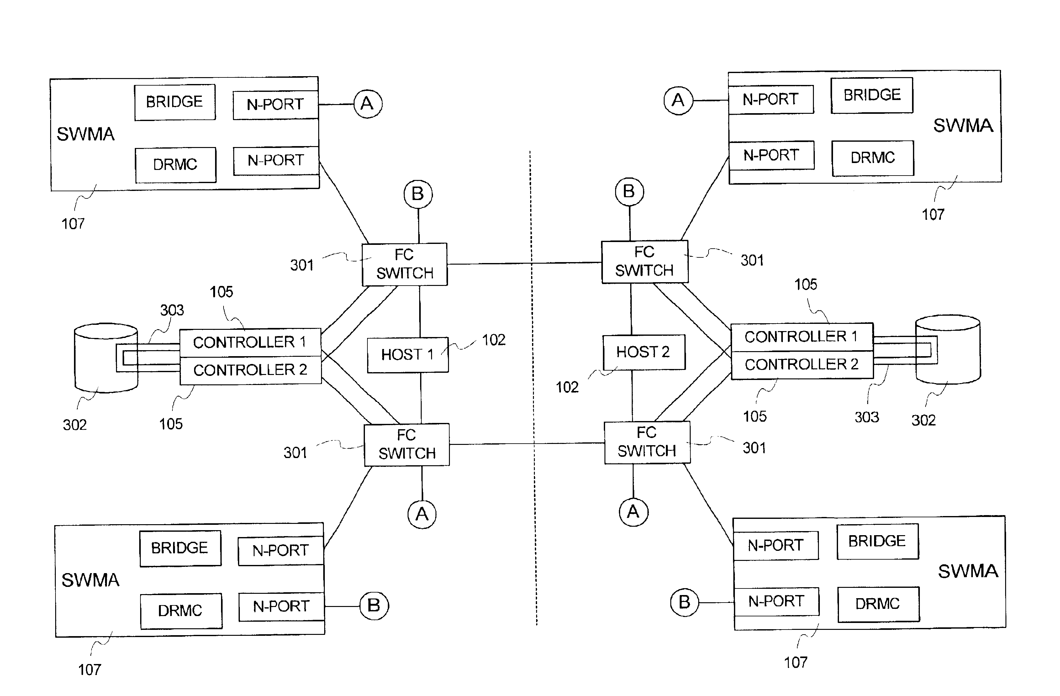
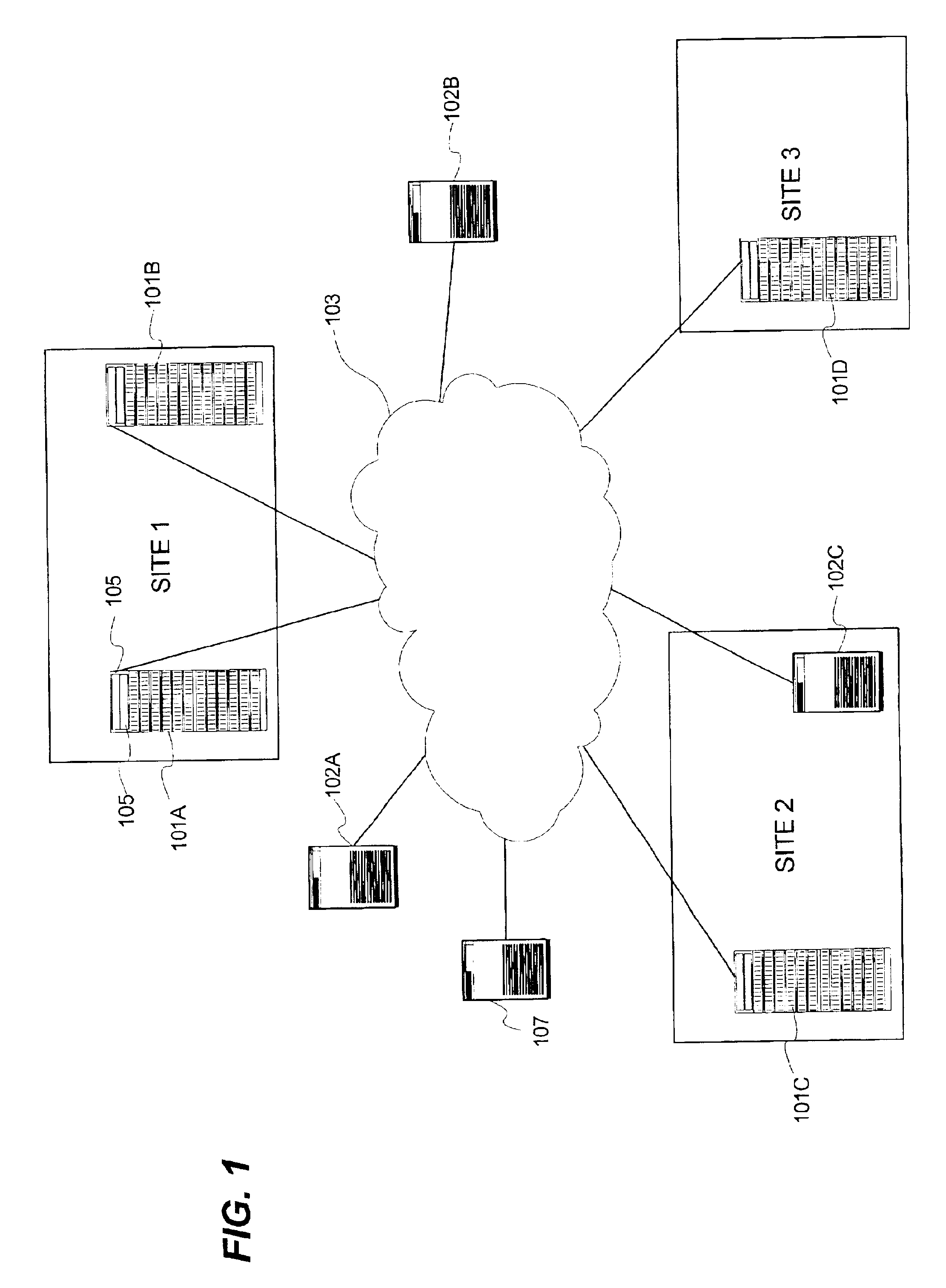
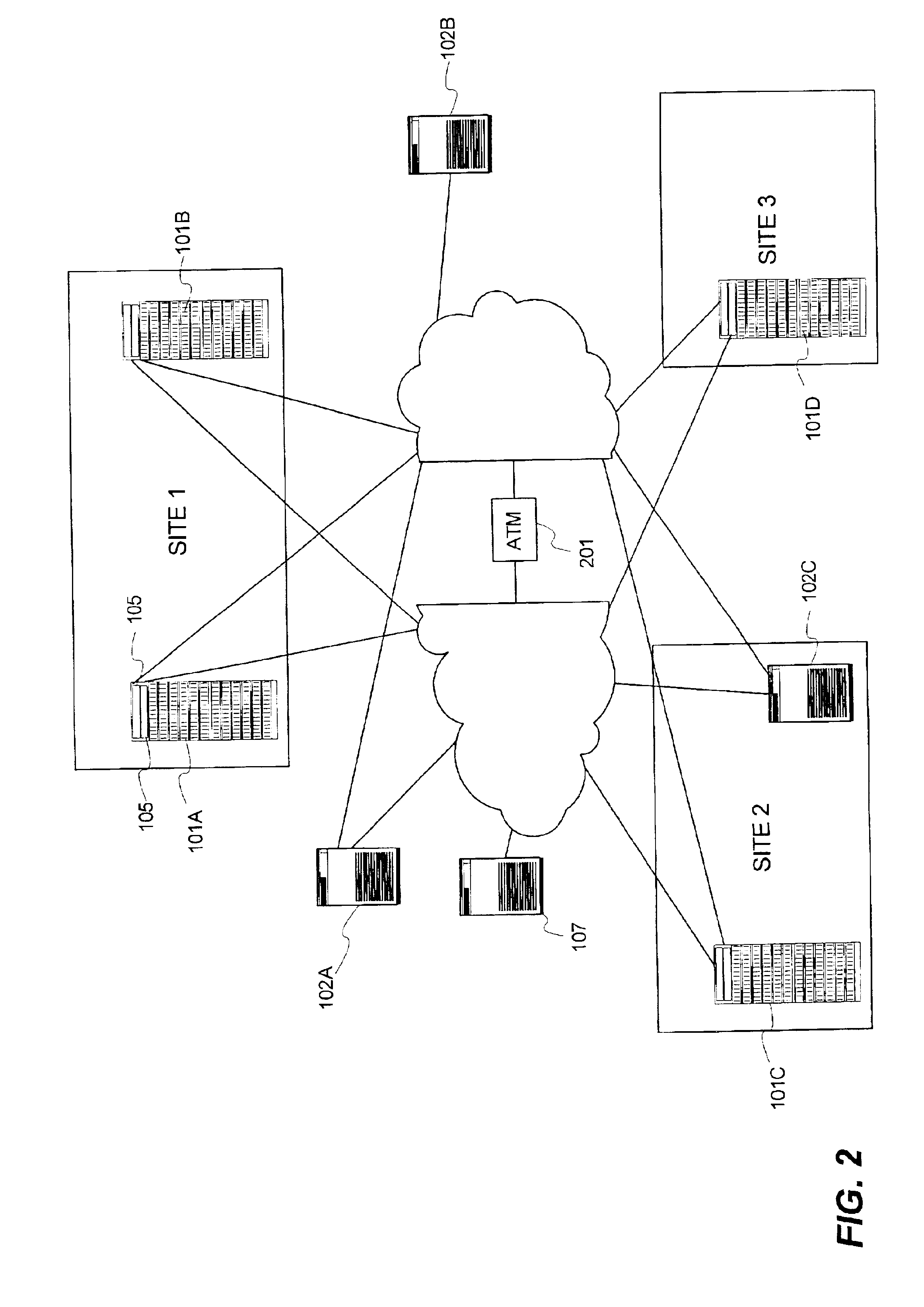
[0021]In general, the present invention describes a data replication management (DRM) architecture comprising a plurality of storage cells interconnected by a data communication network such as a fibre channel fabric. The present invention emphasizes symmetry and peer-cooperative relationships amongst the elements to provide greater flexibility in configuration and operation. Storage cells are for the most part autonomous units of virtualized storage that implement hundreds of gigabytes to terabytes of storage capacity. In accordance with the present invention, each storage cell can act as a source or primary location for data storage, and at the same time act as a destination or secondary location holding a replica data from a primary location of another storage cell. Similarly, the architecture of the present invention seeks to minimize rigid roles placed on interface ports and connections such that all available connections between components can support both host data traffic (e...


PUM


Abstract

A data replication management (DRM) architecture comprising a plurality of storage cells interconnected by a fabric. Flexibility in connectivity is provided by configuring each storage cell port to the fabric to handle both host data access requests and DRM traffic. Each storage cell comprises one or more storage controllers that can be connected to the fabric in any combination. Processes executing in the storage controller find a path to a desired destination storage cell. The discovery algorithm implements a link service that exchanges information related to DRM between the storage controllers. The DRM architecture is symmetric and peer cooperative such that each controller and storage cell can function as a source and a destination of replicated data. The DRM architecture supports parallel and serial “fan-out” to multiple destinations, whereby the multiple storage cells may implement data replicas.

Description

FIELD OF THE INVENTION[0001]The present invention relates generally to error recovery in data storage systems, and more specifically, to a system for providing controller-based remote data replication using a redundantly configured Fibre Channel Storage Area Network to support data recovery after an error event and enhance data distribution and migration.BACKGROUND OF THE INVENTION AND PROBLEM[0002]Recent years have seen a proliferation of computers and storage subsystems. Demand for storage capacity grows by over seventy-five percent each year. Early computer systems relied heavily on direct-attached storage (DAS) consisting of one or more disk drives coupled to a system bus. More recently, network-attached storage (NAS) and storage area network (SAN) technology are used to provide storage with greater capacity, higher reliability, and higher availability. The present invention is directed primarily SAN systems that are designed to provide shared data storage that is beyond the abi...

Claims


Application Information

Patent Timeline
Patent Type & Authority Patents(United States)
IPC IPC(8): G06F11/20H04L29/06H04L29/14H04L69/40
CPCG06F11/201H04L29/06H04L67/1097H04L67/1008H04L67/101H04L67/1034H04L2029/06054H04L67/1002H04L69/40Y10S707/99953Y10S707/99955H04L67/10015H04L67/1001H04L9/40
Inventor LUBBERS, CLARKELKINGTON, SUSANHESS, RANDYSICOLA, STEPHEN J.MCCARTY, JAMESKORGAONKAR, ANUJALEVEILLE, JASON
Owner HEWLETT-PACKARD ENTERPRISE DEV LP
Why Eureka
Try Eureka