
Cluster component network appliance system and method for enhancing fault tolerance and hot-swapping

Inactive Publication Date: 2005-09-20
RACEMI SYST +1
View PDF7 Cites 50 Cited by
  • Summary
  • Abstract
  • Description
  • Claims
  • Application Information

AI Technical Summary

Benefits of technology

[0010]Each of the hot swap connectors of the modules comprises pin connections arranged in a specific pattern. The pins include ground pins, power pins and signal pins. The ground pins of a hot swap connector are connected first to corresponding ground elements of a hot swap mating connector, and the signal pins of the hot swap connector are connected last to corresponding signal elements of the hot swap mating connector so as to reduce brown outs in the computer network appliance.
[0013]The power module of the invention comprises dual DC—DC converters that perform direct conversion of a facility DC voltage to voltages required for normal operation in the modules. Features of the DC—DC converters include: allowing the modules in the computer network appliance to accept DC power directly from a battery backup source without requiring power inverters; higher MTBF than a typical switched power supply; use less power and generate less heat than a typical switched power supply; and provide better efficiency than a typical switched power supply in converting an input voltage to desired operational voltages of the modules.

Problems solved by technology

When a file server or storage server is out of operation, many users are inconvenienced.
In time critical systems such as communications systems, system downtime is both a financial problem as well as a service quality problem.
That is, any downtime means a financial loss and disconnection of service to active lines.
A drawback of hot swapping, however, is it requires trained personnel to insert and / or remove components from a computer system to minimize damages caused by pitting connectors of the components against connectors of the computer system.
Another drawback is electrical noise which can adversely affect the performance of the computer system.
The noise is caused by the change in current at the instance when connection is made between power pins of a component and corresponding elements of the computer system.
The result is voltage transients in the computer system backplane that may cause loss of data, incorrect program execution and damage to delicate hardware components.

Method used


Image

  • Cluster component network appliance system and method for enhancing fault tolerance and hot-swapping
  • Cluster component network appliance system and method for enhancing fault tolerance and hot-swapping
  • Cluster component network appliance system and method for enhancing fault tolerance and hot-swapping

Examples


Embodiment Construction

[0022]The following detailed description presents a description of certain embodiments of the present invention. However, the present invention can be embodied in different ways as defined by the claims. In this description, reference is made to the drawings wherein like parts are designated with like numerals throughout.

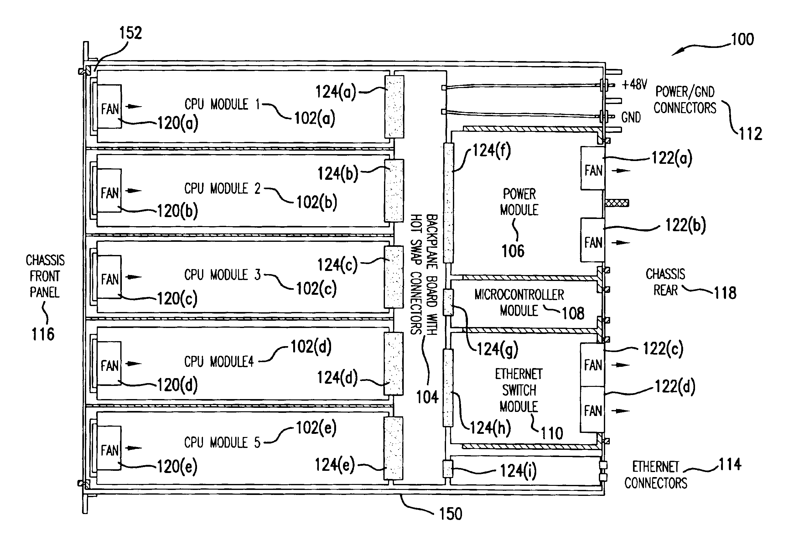
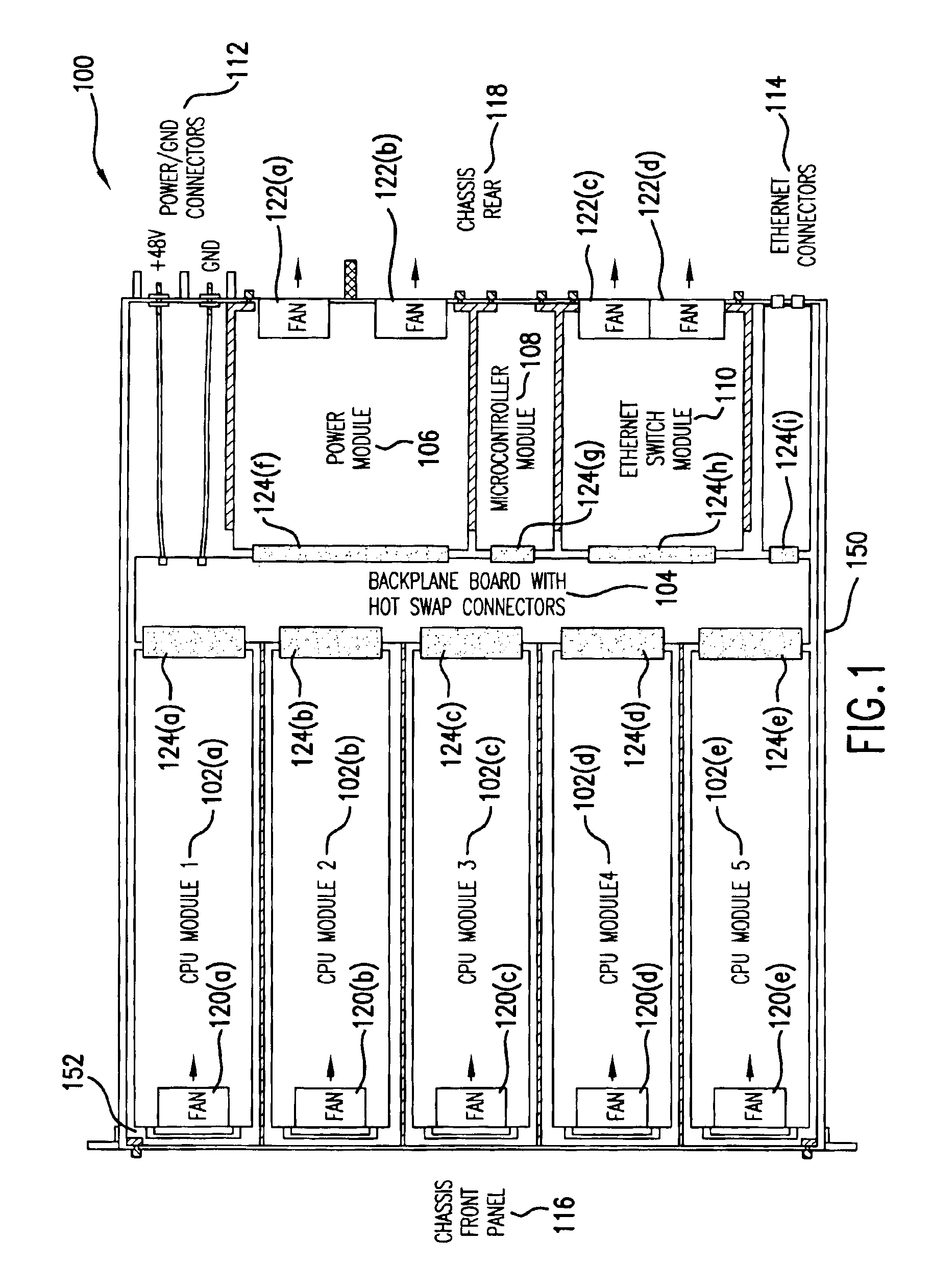
[0023]FIG. 1 is an illustration of a cluster computer network appliance 100 arranged on a chassis 150 in accordance with an embodiment of the invention. The cluster computer network appliance 100 includes a plurality of CPU modules 102(a)-102(e), a passive backplane board 104 with hot swap mating connectors 124(a)-124(i), a power module 106, a microcontroller module 108, an ethernet switch module 110, power / ground connectors 112 and ethernet connectors 114. The cluster computer network appliance 100 fits in a 1.75″ tall (1RU) metal chassis that fits in a standard 19″ rack. The chassis 150 includes a fold down front panel 116 and supports the modules and backplane bo...


PUM


Abstract

Packaging a hot-swappable server module (server blade) in a computer network appliance with shared, hot-swappable power, network, and management modules to provide highly available computer capacity. Distributing power between hot-swappable modules using single DC input voltage.

Description

[0001]This application claims priority from U.S. Provisional Application Ser. No. 60 / 248,834, filed Nov. 16, 2000. The entirety of that provisional application is incorporated herein by reference.BACKGROUND OF THE INVENTION[0002]1. Field of the Invention[0003]This invention generally relates to fault tolerant computer systems and, more specifically, to a system and method for enhancing fault tolerance and hot swapping in computer systems.[0004]2. Related Art[0005]Computer systems such as file servers and storage servers in computer networks are relied upon by large numbers of users. When a file server or storage server is out of operation, many users are inconvenienced. Thus, technology has been developed which supports maintenance and service of computer systems while they remain operational. One part of maintenance and service includes the replacement of components in the computer systems. “Hot swap” technology allows the replacement of components without turning off the power or ...

Claims


Application Information

Patent Timeline
IPC IPC(8): G06F1/18G06F9/445H04L29/06H04L29/08
CPCG06F1/18G06F9/4405H04L29/06H04L67/1097H04L67/34H04L69/329H04L9/40
Inventor DERRICO, JOEL BRIANFREET, PAUL JONATHAN
Owner RACEMI SYST
Learn More