Cogeneration device

a cogeneration device and technology of cogeneration water, applied in the direction of ventilation systems, heating types, steam generation using hot heat carriers, etc., can solve the problem of no conventional system in which the thermal energy is effectively recovered from such drain water, and achieve the effect of improving the efficiency of recovering waste thermal energy, and facilitating the recovery of waste thermal energy

Inactive Publication Date: 2005-09-27
HONDA MOTOR CO LTD
View PDF8 Cites 11 Cited by
  • Summary
  • Abstract
  • Description
  • Claims
  • Application Information

AI Technical Summary

Benefits of technology

[0008]Furthermore, in accordance with a second aspect of the present invention, in addition to the first aspect, there is provided a cogeneration system wherein the system further includes a pure water generator for generating pure water for supply to the waste heat boiler, and a waste-water-heating heat exchanger for heating waste water from the pure water generator by heat exchange with the exhaust gas discharged from the waste heat boiler, the drain water recovery / supply means including a tank in which the waste water heated by the waste-water-heating heat exchanger and the drain water are mixed. In accordance with this arrangement, even when the drain water generated from the exhaust gas is alkaline, since the alkalinity can be weakened by dilution due to the mixing with the waste water from the pure water generator within the tank, its application can be extended by enabling the water within the tank to be utilized effectively in more appliances.
[0009]Moreover, in accordance with a third aspect of the present invention, in addition to the second aspect, there is provided a cogeneration system wherein the drain water recovery / supply means is arranged so as to be able to recover drain water generated from the exhaust gas cooled by heat exchange with the waste water in the waste-water-heating heat exchanger, and to supply the drain water to the appliance. In accordance with this arrangement, the water contained in the exhaust gas can be recovered more effectively, thereby further improving the efficiency of recovery of the waste thermal energy.
[0010]Furthermore, in accordance with a fourth aspect of the present invention, in addition to the second or third aspect, there is provided a cogeneration system wherein a bypass that bypasses the air-heating heat exchanger and switches over between opened and closed states according to the outside air temperature is connected, on either side of the air-heating heat exchanger, to an air conditioner air supply passage connected to the air conditioner. In accordance with this arrangement, changes according to the season in the amount of drain water and the temperature of the air conditioner that are required can be accommodated.
[0011]Moreover, in accordance with a fifth aspect of the present invention, in addition to the first or third aspect, there is provided a cogeneration system wherein the appliance is an air conditioner air humidifier. In accordance with this arrangement, the water contained in the exhaust gas can be recovered effectively and used in the air conditioner air humidifier.
[0012]Furthermore, in accordance with a sixth aspect of the present invention, in addition to the first or third aspect, there is provided a cogeneration system wherein the appliance is a hot water washer. In accordance with this arrangement, the water contained in the exhaust gas can be recovered effectively and used in the hot water washer.
[0013]Moreover, in accordance with a seventh aspect of the present invention, in addition to any one of the first to sixth aspects, there is provided a cogeneration system wherein the waste heat boiler is connected to a combustor of a gas turbine, which is the prime mover, to thereby supply a part of steam acquired by the waste heat boiler to the combustor. In accordance with this arrangement, by increasing the weight of a gas fed to the turbine via the combustor and increasing the rotational speed of the turbine, the capacity of the generator can be increased, and the steam returned to the gas turbine can be recovered effectively as drain water.

Problems solved by technology

In the air-heating heat exchanger, which carries out heat exchange with the exhaust gas on the downstream side of the waste heat boiler, part of the water contained in the exhaust gas is condensed by being cooled by heat exchange with the air that is to be fed into the air conditioner, and is discharged as drain water, and although the temperature of the drain water is expected to be comparatively high, there is no conventional system in which the thermal energy is recovered effectively from such drain water.

Method used


Image

  • Cogeneration device
  • Cogeneration device
  • Cogeneration device

Examples


Embodiment Construction

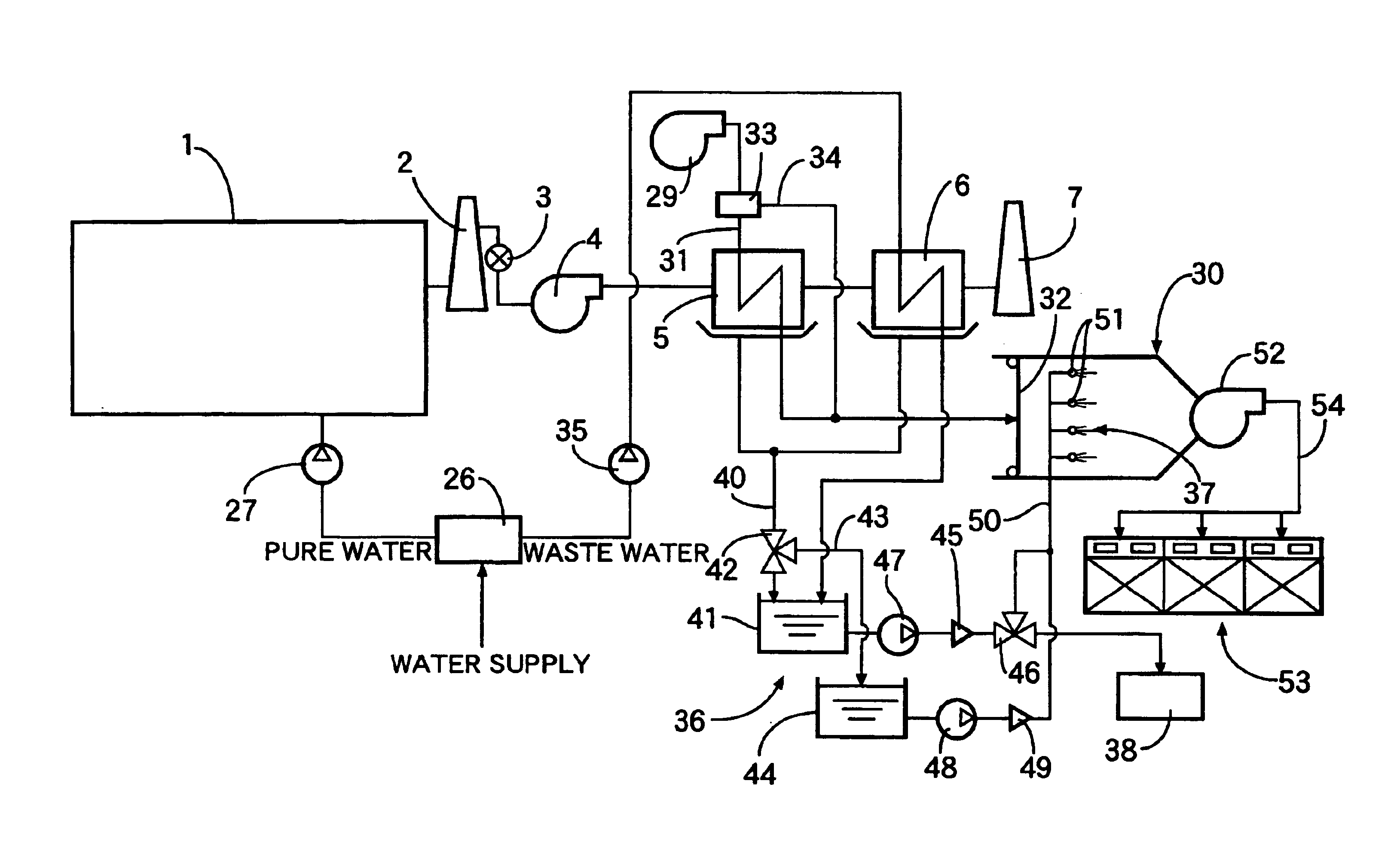
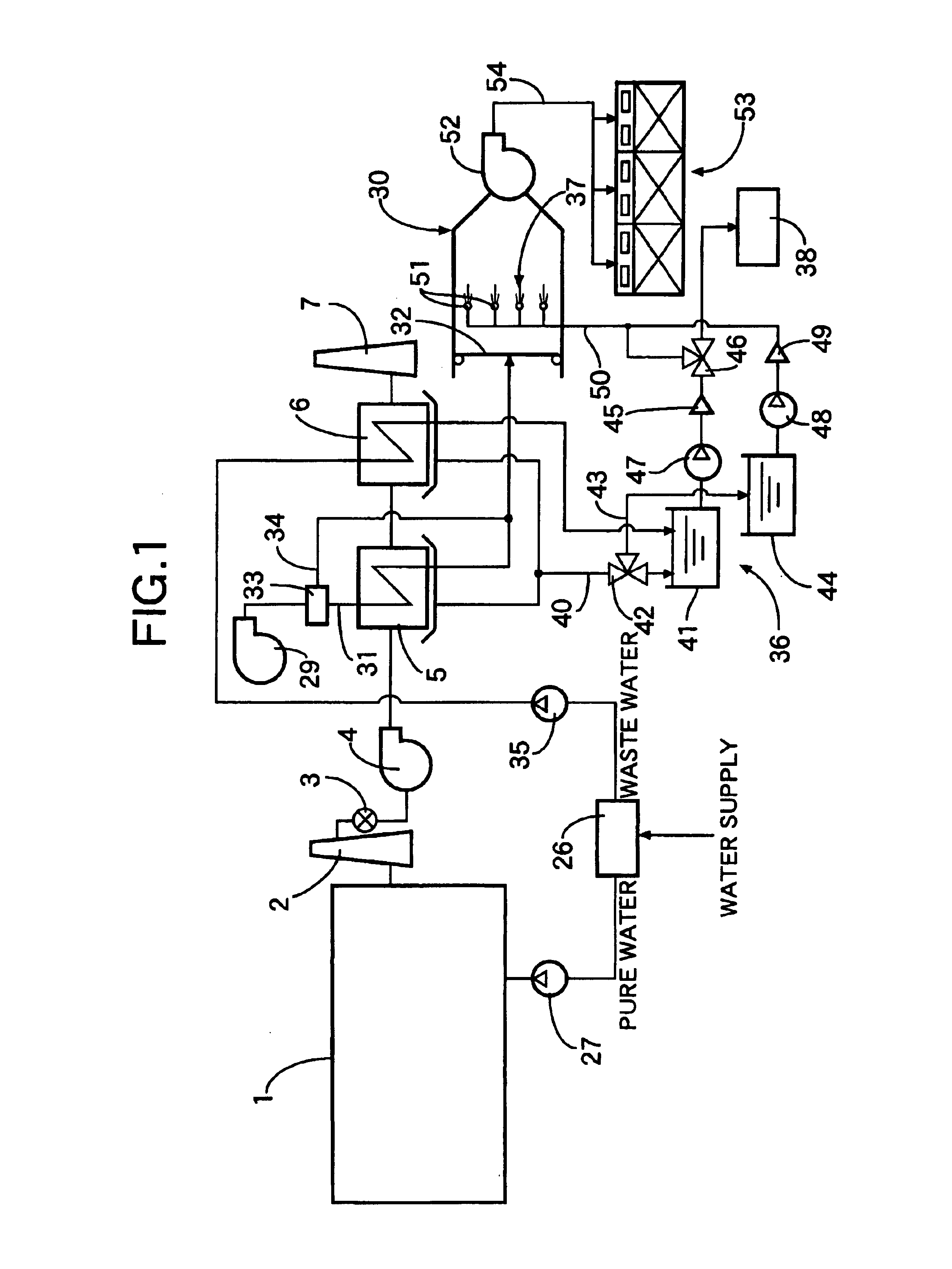
[0015]Modes for carrying out the present invention are explained below by reference to one embodiment of the present invention illustrated in FIG. 1 and FIG. 2. Referring firstly to FIG. 1, exhaust gas discharged from a generator system 1 is directed to a stack 2. The induction side of an induction fan 4 is connected to the stack 2 via an open / close valve 3, and the discharge side of the induction fan 4 is connected to a stack 7 via an air-heating heat exchanger 5, and a waste-water-heating heat exchanger 6 connected to the downstream side of the air-heating heat exchanger 5.

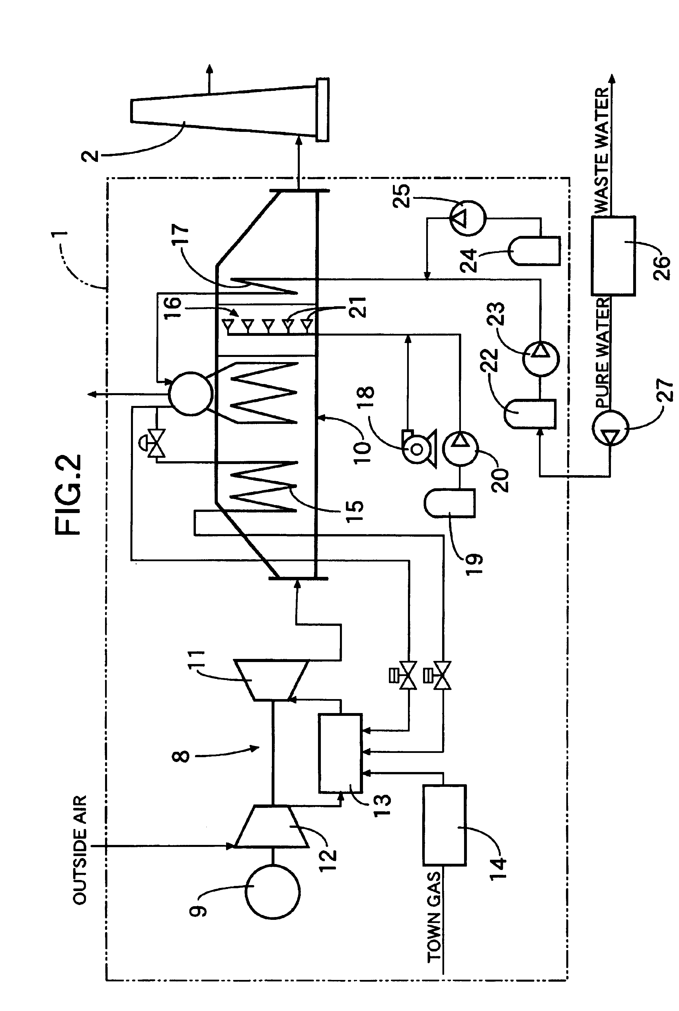
[0016]In FIG. 2, the generator system 1 includes a gas turbine 8, which is a prime mover, a generator 9 that is driven by the gas turbine 8, and a waste heat boiler 10 that recovers thermal energy by heat exchange with exhaust gas discharged from a combustor of the gas turbine 8. The exhaust gas discharged from the waste heat boiler 10 is directed to the stack 2.

[0017]The gas turbine 8 includes a turbine 11, a c...


PUM


Abstract

A cogeneration system is provided which includes a prime mover for obtaining power for driving a generator by combustion of a fuel, a waste heat boiler for recovering thermal energy from exhaust gas discharged from the prime mover, and a heat exchanger for heating air that is to be fed into an air conditioner by heat exchange with the exhaust gas discharged from the waste heat boiler. Drain water that is generated from the exhaust gas cooled by heat exchange in the air-heating heat exchanger (5) with the air that is to be fed into the air conditioner (30) is recovered by drain water recovery/supply means (36). The drain water recovery/supply means (36) supplies the drain water thus recovered to appliances (37, 38) that require comparatively high temperature water. Thermal energy can thus be recovered effectively from the drain water discharged from the heat exchanger on the downstream side of the waste heat boiler, thereby improving the efficiency of recovery of waste heat energy.

Description

CROSS-REFERENCE TO RELATED APPLICATION[0001]This application is a National Stage entry of International Application No. PCT / JP02 / 00385, filed Jan. 21, 2002. The disclosure of the prior application is hereby incorporated herein in its entirety by reference.FIELD OF THE INVENTION[0002]The present invention relates to a cogeneration system that includes a prime mover for obtaining power for driving a generator by combustion of a fuel, a waste heat boiler for recovering thermal energy from exhaust gas discharged from the prime mover, and an air-heating heat exchanger for heating air that is to be fed into an air conditioner by heat exchange with the exhaust gas discharged from the waste heat boiler.BACKGROUND ART[0003]Such a cogeneration system is known from, for example, Japanese Patent Application Laid-open No. 4-342807 in which, after the thermal energy of exhaust gas discharged from a prime mover is recovered by a waste heat boiler, air that is to be used in an air conditioner is he...

Claims


Application Information

Patent Timeline
Patent Type & Authority Patents(United States)
IPC IPC(8): F01K21/00F01K21/04F02G5/00F02G5/02F02G5/04F22B1/18F23L17/14F24F3/00F24H1/00
CPCF01K21/047F02G5/00Y02E20/14Y02T10/166Y02T10/12F01K23/10
Inventor HAYAKAWA, TSUTOMUSAMEKAWA, KEIICHIKUME, YASUHIROMUKANO, YUUJI
Owner HONDA MOTOR CO LTD
Why Eureka
Try Eureka