
Track and hinge for a boat ladder

Inactive Publication Date: 2005-09-27
CHUSTAK DANIEL A
View PDF13 Cites 34 Cited by
  • Summary
  • Abstract
  • Description
  • Claims
  • Application Information

AI Technical Summary

Benefits of technology

[0003]The track and hinge arrangement of the present invention provides an ability for a ladder to be moved behind an enclosure on the deck of a water craft when the ladder is in an up position and allows the ladder to slide in a rail to an inline location with respect to a gate in the enclosure and rotated 180° to a down position and permit ingress / egress between the deck and a body of water.
[0004]According to this invention, the track and hinge arrangement is characterized by a rail having a length that extends from a first end located on the deck adjacent the opening of the gate for the enclosure to a second end located on the deck a fixed distance past the opening. The rail has an axial space that extends from the first end to the second end with an axial slot that is located in a top surface of the rail. The axial slot extends the exterior surface into the axial space from the first end to the second end with a dimension that is smaller than a width of the axial space such that first and second lips are defined along top surface of the rail. The rail has a uniform shape and forms a threshold in the opening of the gate such that it does not interior with walking through the gage. A first connector has a first head that is located in the axial space with a first shaft that extends through the axial slot that is connected to a first strap of a first hinge member and a second connector has a first head that is located in the axial space with a first shaft that extends through the axial slot that is connected to a first strap of a second hinge member. The first strap of the first hinge is connected to a second strap by a first pin while the first strap of the second hinge is connected to a second strap by a second pin. The second strap of the first hinge is connected to a first leg of the ladder and the second strap of the second hinge is connected to a second leg of the ladder. The first straps are aligned in a horizontal position with respect to the deck while the first and second pins allow the second straps to pivot between the up and down positions to allow the ladder to be moved between a first vertical position adjacent inside of the side rail to a second vertical position adjacent the outside of the side rail. When the ladder is an up position it may be moved in the rail past the gate to be hidden behind the side rail and as a result does not detract from the external appearance of the watercraft. In addition, once the ladder is deployed in the down position, the gate may be closed and as a result any children could move about the deck and be protected from accidentally stepping into the water.
[0007]A further advantage of this invention resides in the positioning of the ladder along the side rather than on the rear such that the driver of a boat can have eye to eye contact with a person in the water or skiing behind the boat and there is a reduction in the possible contact with a propeller of boat.

Problems solved by technology

When the ladder is located in the gateway, the gate can not be closed and it is possible that ladder may be dislodged from the deck by a wave created by another boat passing the moored watercraft and as a result a ladder often sinks to the bottom the body of water.
Unfortunately, a ladder stored inside a seat is often not accessible from the water and nor convenient for speedy installation in the gateway.
While this type structure functions in an adequate manner, a track may be damaged if the watercraft should engage the dock at a high speed.
In addition, since the ladder and track is located on the exterior of the deck some boat owners have a concern that it detracts from the overall sleek appearance of the watercraft.

Method used


Image

  • Track and hinge for a boat ladder
  • Track and hinge for a boat ladder
  • Track and hinge for a boat ladder

Examples


Embodiment Construction

[0022]Throughout the specification when a same component is used in more than one location it may be described only once but will be identified by the number plus when necessary for use in the other location.

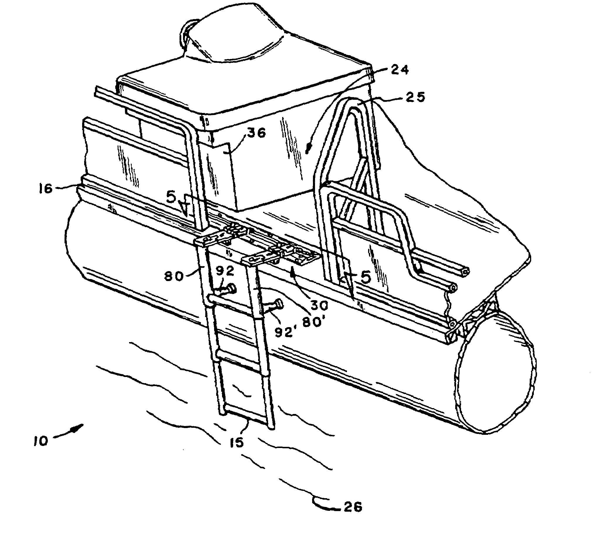
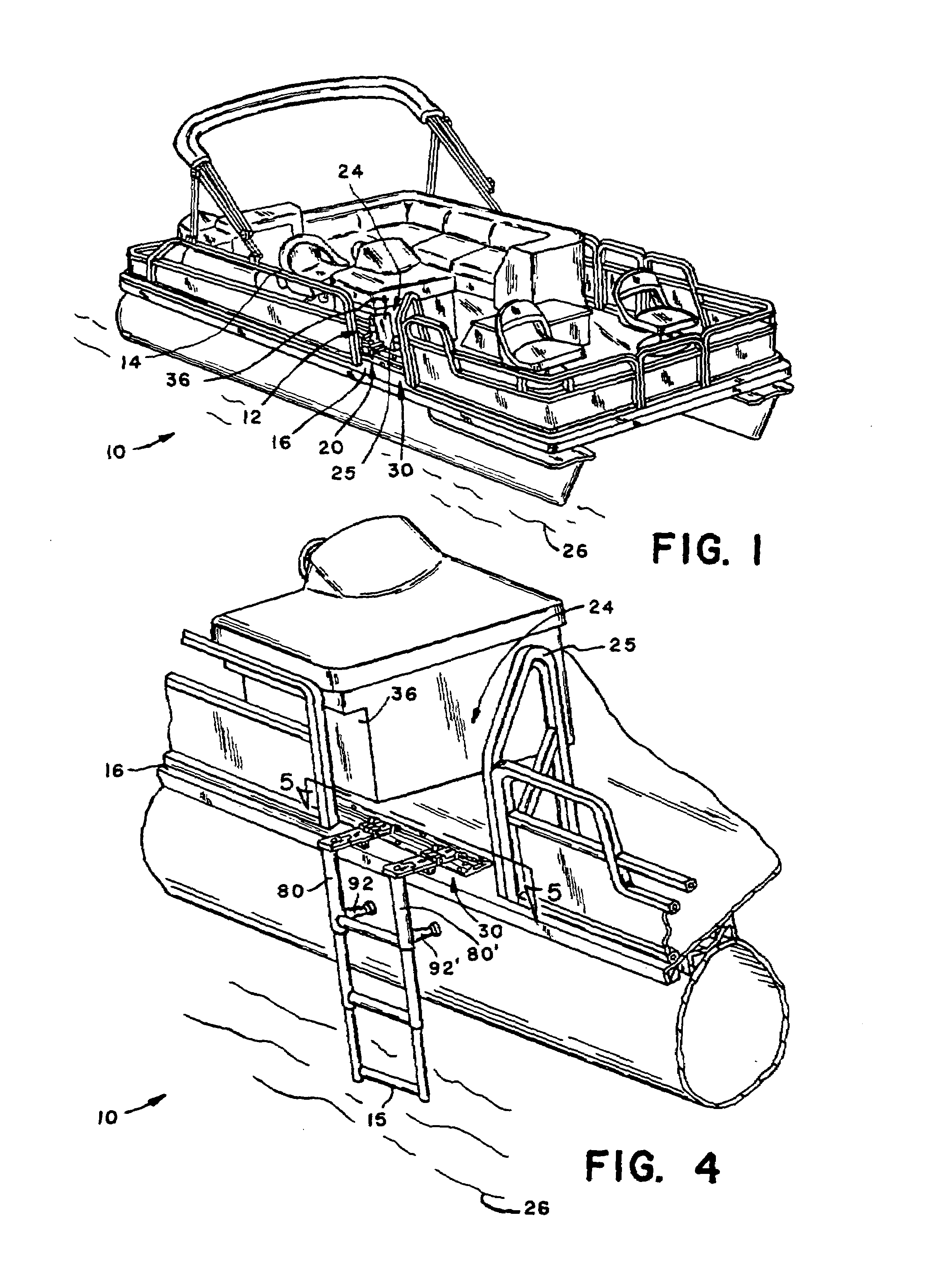
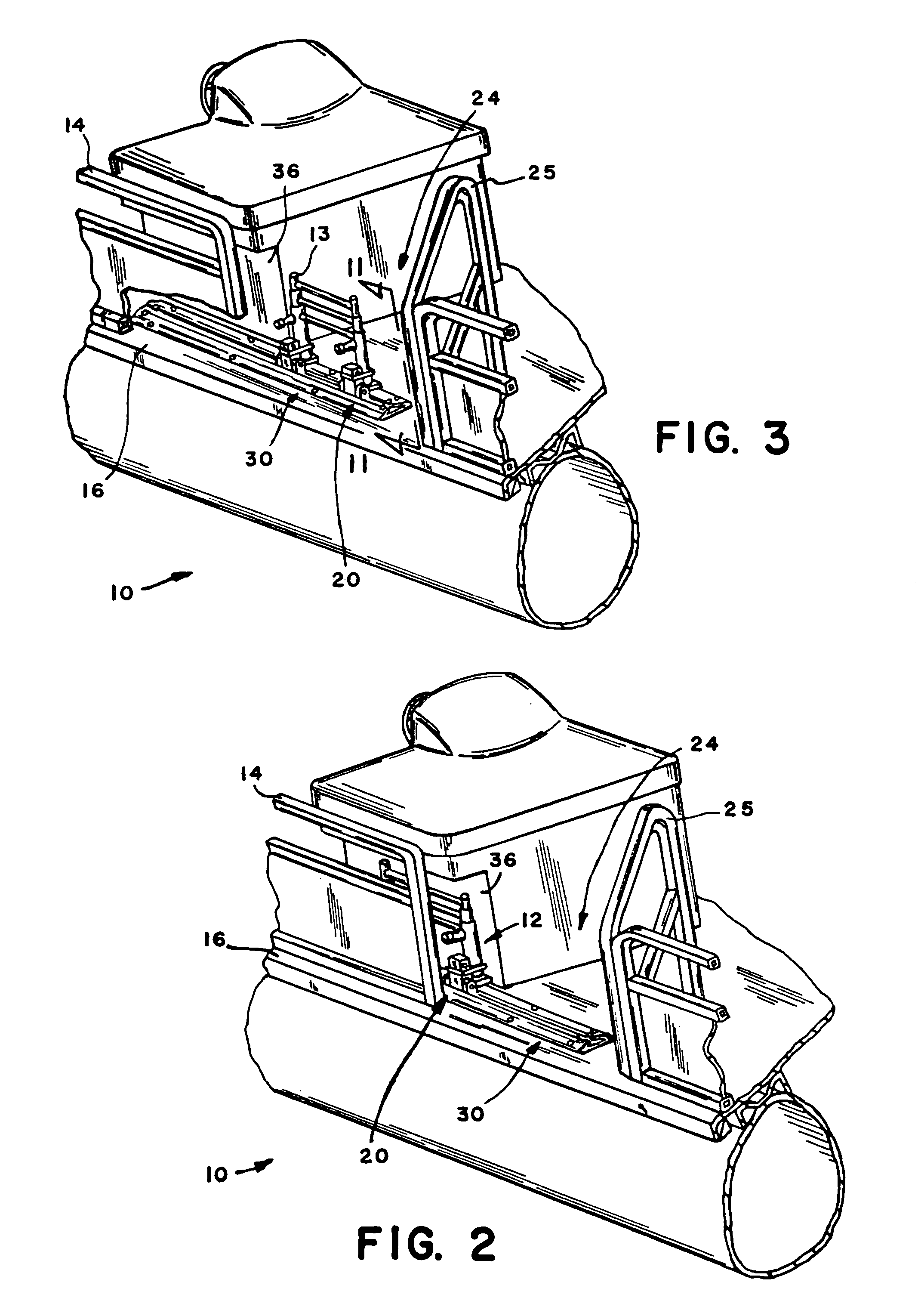
[0023]FIGS. 1 and 2 provide a schematic illustration of a watercraft 10 having a ladder 12 that is located in a pocket 36 behind an enclosure 14 on the deck 16 in accordance with the present invention. The ladder 12 is retained on the deck 16 by a track and hinge arrangement 20 that is attached to the deck 16 in a manner that the ladder 12 may be moved from the pocket 36 behind the enclosure 14 to a position in alignment with an opening 24 of a gate 25 in the enclosure 14 as shown in FIG. 3 and rotated from an up position to a down position as shown in FIG. 4 to permit ingress / egress from a body of water 26 onto the deck 16. The ladder 12 is designed to be retracted and stowed as shown in FIGS. 1 and 2 when the watercraft is moving in the body of water 26 and as a result does no...


PUM


Abstract

A ladder system through which a ladder is retained on a deck of a watercraft by a track arrangement and positioned at a first location in an opening for an enclosure where the ladder is substantially vertical to the side of the watercraft to permit ingress / egress of a person between a body of water and the deck. The ladder is connected to a rail of the track arrangement by a first and second hinges that permits the ladder to be rotated from the vertical position along the side of the watercraft to a position inside of the enclosure. The ladder may thereafter be moved from the opening to a location adjacent the gate and behind the enclosure to conceal and stow the ladder such that the exterior surface of the watercraft along the enclosure is substantially uniform from stem to stern.

Description

[0001]This invention relates to a track through which a ladder is attached to a deck to allow egress from a body of water into a water craft and whereby the ladder is hidden behind an enclosure when the water craft is traveling through the body of water.BACKGROUND OF THE INVENTION[0002]Pontoon boats are a popular watercraft with many people as they can be used for many different activities such as fishing, trolling, tubing, skiing, cruising and mooring. The decks for pontoon boats most often provided with an enclosure that extends about 2–3 feet above the deck to offer protection against stepping into the water or being ejected into the water during movement of the boat in a body of water. The enclosure has at least one and more often two gates to allow a person to directly walk from a pier onto the deck with gate matching the enclosure such that a uniform appearance is provided from the front to the rear of the boat. A popular activity for the use of a pontoon boat is to moor in a ...

Claims


Application Information

Patent Timeline
IPC IPC(8): E04G3/00E06C9/00B63B17/00B63B17/02B63B27/14E06C9/12
CPCB63B27/146E06C9/12
Inventor CHUSTAK, DANIEL A.
Owner CHUSTAK DANIEL A
Features
  • Generate Ideas
  • Intellectual Property
  • Life Sciences
  • Materials
  • Tech Scout
  • Unparalleled Data Quality
  • Higher Quality Content
  • 60% Fewer Hallucinations
Learn More