Test apparatus for power circuits of an electrical distribution device

a technology for testing apparatus and electrical distribution devices, which is applied in the direction of instruments, heat measurement, thermometers using value differences, etc., can solve problems such as unstable aluminum wire conductors to the terminals of wiring devices, affecting the safety of electrical distribution devices, and melting of wire insulation

Inactive Publication Date: 2005-09-27
EATON INTELLIGENT POWER LTD
View PDF29 Cites 42 Cited by
  • Summary
  • Abstract
  • Description
  • Claims
  • Application Information

AI Technical Summary

Problems solved by technology

The resulting temperature rise at this connection point can melt the wire's insulation and damage the receptacle.
The connection of an aluminum wire conductor to the terminal of a wiring device is unstable, since the aluminum, over time, tends to flow, thus, making the aluminum wire-to-terminal a high resistance connection.
Unfortunately, this is not true.
Also, the lack of wide spread public knowledge of the glowing contact problem may follow from the fact that there has been no known solution to this problem.
By Paschen's laws, it is not possible to create a sustained copper-to-copper through air arc discharge in a 120 VRMS circuit with a resistive load.
There can be a spark whenever an electrical contact is broken due to local heating at the break point.
Copper oxide has a number of characteristics which, when combined, creates a hazard.
As the connection heats, the current tends to concentrate into a relatively narrow region, thereby resulting in a very high current density and temperature.
This can result in either an arcing fault or a ground fault if the bare glowing wire contacts another conductor.
Second, the heat resulting from the glowing contact fault flows into the receptacle and causes the plastic housing of the receptacle to melt.
As the plastic melts, the receptacle loses its mechanical integrity and, thus, the electrical isolation between conductors is compromised.
This may ultimately lead to either a line-to-ground fault or a neutral-to-ground fault.
The existence of a glowing contact, therefore, is not reliably detectable by a conventional upstream current protective device (e.g., a conventional circuit breaker or fuse).
However, significant damage may result to both the wire's insulation and the receptacle.

Method used


Image

  • Test apparatus for power circuits of an electrical distribution device
  • Test apparatus for power circuits of an electrical distribution device
  • Test apparatus for power circuits of an electrical distribution device

Examples


Embodiment Construction

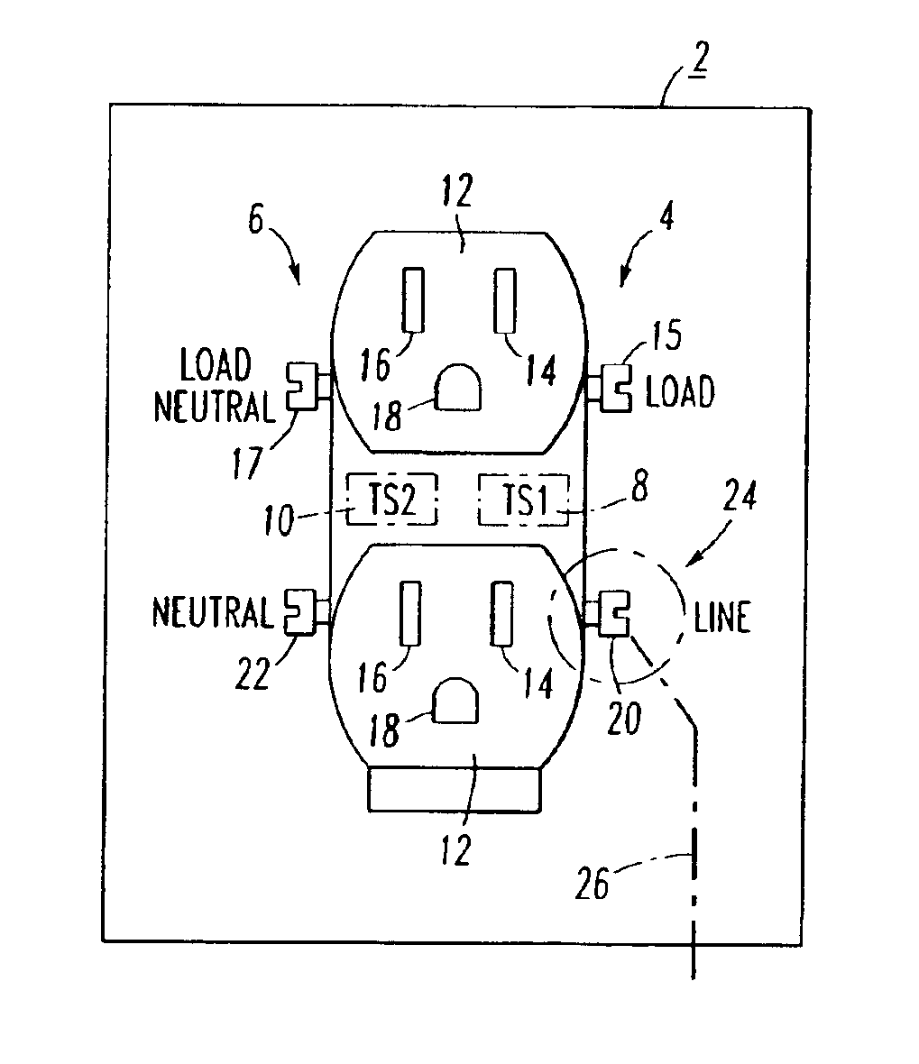
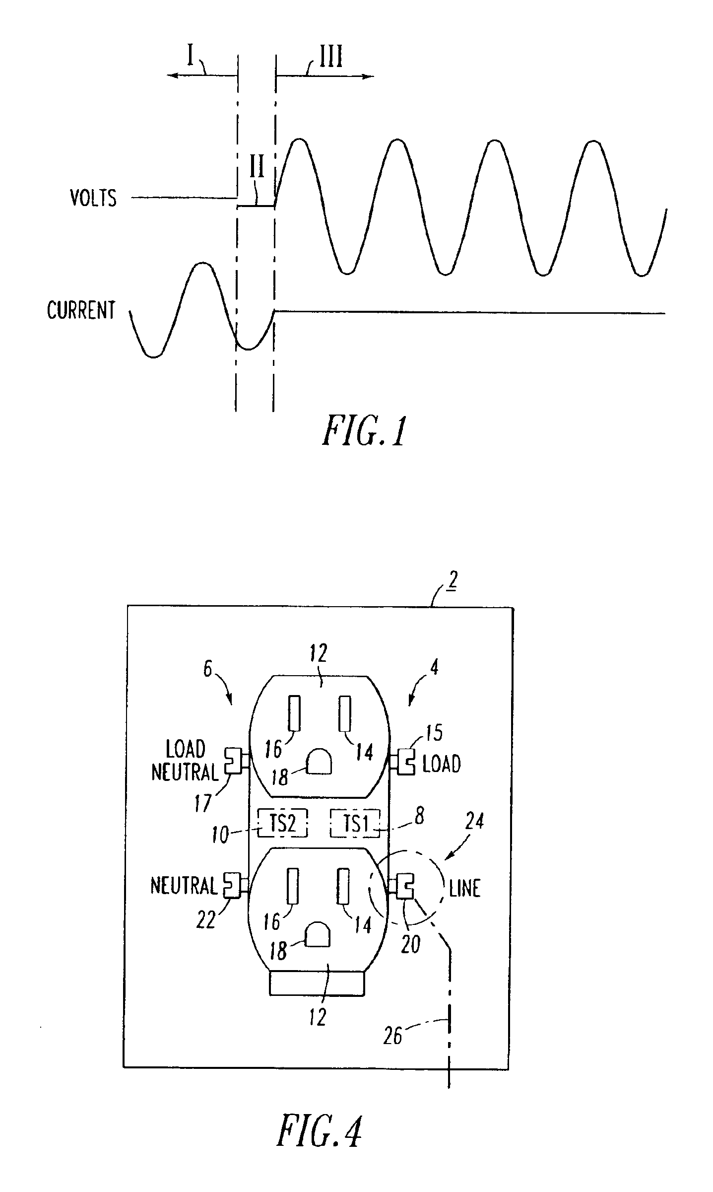
[0036]Referring to FIGS. 4 and 5, an electrical distribution device, such as a receptacle 2, and a tester 3 for that device are respectively shown. The receptacle 2 includes a line circuit 4 having a first temperature and a neutral circuit 6 having a second temperature. In accordance with the present invention, the tester 3 includes a first temperature sensor (TS1) 8, which senses the first temperature of the line circuit 4, and a second temperature sensor (TS2) 10, which senses the second temperature of the neutral circuit 6. Although the disclosed receptacle 2 is a conventional ground fault circuit interrupter (GFCI), any conventional electrical distribution device, such as a conventional receptacle outlet (not shown) having line and neutral, or line, neutral and ground connections, may be employed.

[0037]As is conventional, the receptacle 2 includes one or more three-conductor outlets 12 having female load, load neutral and ground terminals 14, 16, and 18, respectively. The recept...


PUM

PropertyMeasurementUnit
voltageaaaaaaaaaa
voltageaaaaaaaaaa
voltageaaaaaaaaaa

Abstract

A glowing contact or high resistance test device includes a housing and first and second circuits substantially within the housing. The first and second circuits include first and second electrical plugs disposed from the housing and adapted to electrically engage and thermally communicate with line and neutral circuits, respectively, of an electrical receptacle. First and second diode temperature sensors are proximate the first and second circuits and the first and second electrical plugs, respectively. The first and second sensors output first and second signals representative of the first and second temperatures of the line and neutral circuits, respectively. An amplifier circuit determines a difference between the first and second signals. A window comparator circuit includes a light emitting diode, which displays an indication signal when the absolute value of the difference exceeds a predetermined value.

Description

CROSS-REFERENCE TO RELATED APPLICATION[0001]This application is related to commonly assigned, concurrently filed U.S. patent application Ser. No. 10 / 192,580, filed Jul. 10, 2002, entitled: “Electrical Switching Apparatus Including Glowing Contact Protection”.BACKGROUND OF THE INVENTION[0002]1. Field of the Invention[0003]The invention relates to testing of electrical systems and, more particularly, to apparatus for testing of electrical distribution devices, such as, for example, a receptacle outlet or a wiring device.[0004]2. Background Information[0005]A glowing contact is a high resistance connection, which can form at the interface of a copper wire and a screw terminal, for example, of a receptacle. The resulting temperature rise at this connection point can melt the wire's insulation and damage the receptacle. It is desirable to be able to detect this condition and interrupt the current before the glowing contact fault progresses to a hazardous condition.[0006]The hazard associ...

Claims


Application Information

Patent Timeline
Patent Type & Authority Patents(United States)
IPC IPC(8): G01K7/01G01K3/14G01K3/00G01K7/42
CPCG01K3/14G01K7/01G01K7/42
Inventor ENGEL, JOSEPH C.
Owner EATON INTELLIGENT POWER LTD
Why Eureka
Try Eureka