Rolling bearing device and ring with sensor for the rolling bearing device

a technology of rolling bearing and sensor, which is applied in the direction of shaft assembly, mechanical apparatus, instruments, etc., can solve the problems of limiting the freedom of laying out parts, affecting the life of bearings, and bearings that are often splashed with water, so as to reduce the formation of artificial parts and be easily attached.

Inactive Publication Date: 2005-09-27
NSK LTD
View PDF28 Cites 63 Cited by
  • Summary
  • Abstract
  • Description
  • Claims
  • Application Information

AI Technical Summary

Benefits of technology

[0016]Accordingly, an object of the present invention is to provide a rolling bearing with sensor and a ring with sensor for the rolling bearing device which minimizes the formation of any artificial part on a bearing mounting part of a bearing housing, and which may easily be attached to an equipment that already exists.

Problems solved by technology

The vibration and temperature will adversely affect the lifetime of the bearing.
When the rolling bearing is mounted on a machine used outdoors, such an automobile, a railroad car, or a construction machine, the bearing is frequently splashed with water when it runs in the rain or on a road with puddles.
The protruded part is likely to restrict a freedom in laying out parts.
Accordingly, when it is located apart from an object to be detected, the detection is likely to contain noticeable noise.
In the case of the temperature sensor, with increase of a distance of the sensor to a heat source, its thermal conduction time becomes longer, and the sensing operation is affected by another heat source or sources, resulting in producing an incorrect sensed value.
Also for the humidity detecting, it is necessary to detect humidity within the bearing space located inside the bearing; otherwise, it is impossible to correctly evaluate a degree of water entrance.
A complicated mechanism is required for supplying electric power to the sensor provided on the rotating part.

Method used


Image

  • Rolling bearing device and ring with sensor for the rolling bearing device
  • Rolling bearing device and ring with sensor for the rolling bearing device
  • Rolling bearing device and ring with sensor for the rolling bearing device

Examples


first embodiment

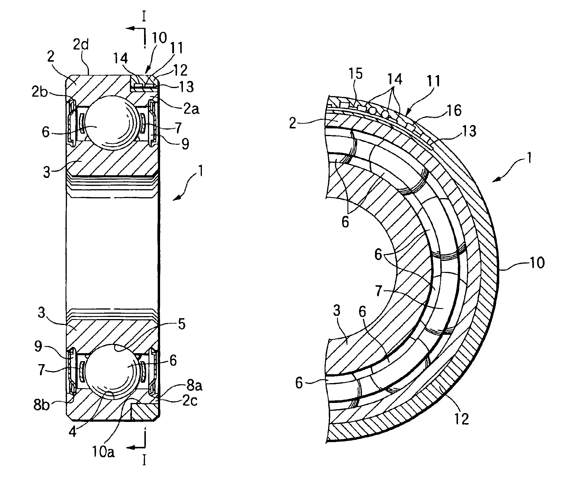
[0071]the present invention will be described with reference to FIGS. 1A and 1B. A bearing 1 shown in FIGS. 1A and 1B is a single-row deep groove ball bearing. The bearing 1 includes an outer ring 2 and an inner ring 3, which are examples of a bearing ring. An outer raceway 4, while being recessed, is formed at a central part of the inner peripheral surface of the outer ring 2. An inner raceway 5, while being recessed, is formed at a central part of the outer peripheral surface of the inner ring 3. A plurality of balls 6 as rolling elements are retained with a retainer 7 in the circumferential direction at equal intervals, while being equianguiarly disposed and in rolling contact with the outer raceway 4 and the inner raceway 5. Shield mounting grooves 8a and 8b are respectively provided at the inner peripheral surfaces of both ends 2a and 2b of the outer ring 2 as viewed in the widthwise direction. Shields 9 are fitted to those grooves 8a and 8b.

[0072]An annular groove 10, as show...

second embodiment

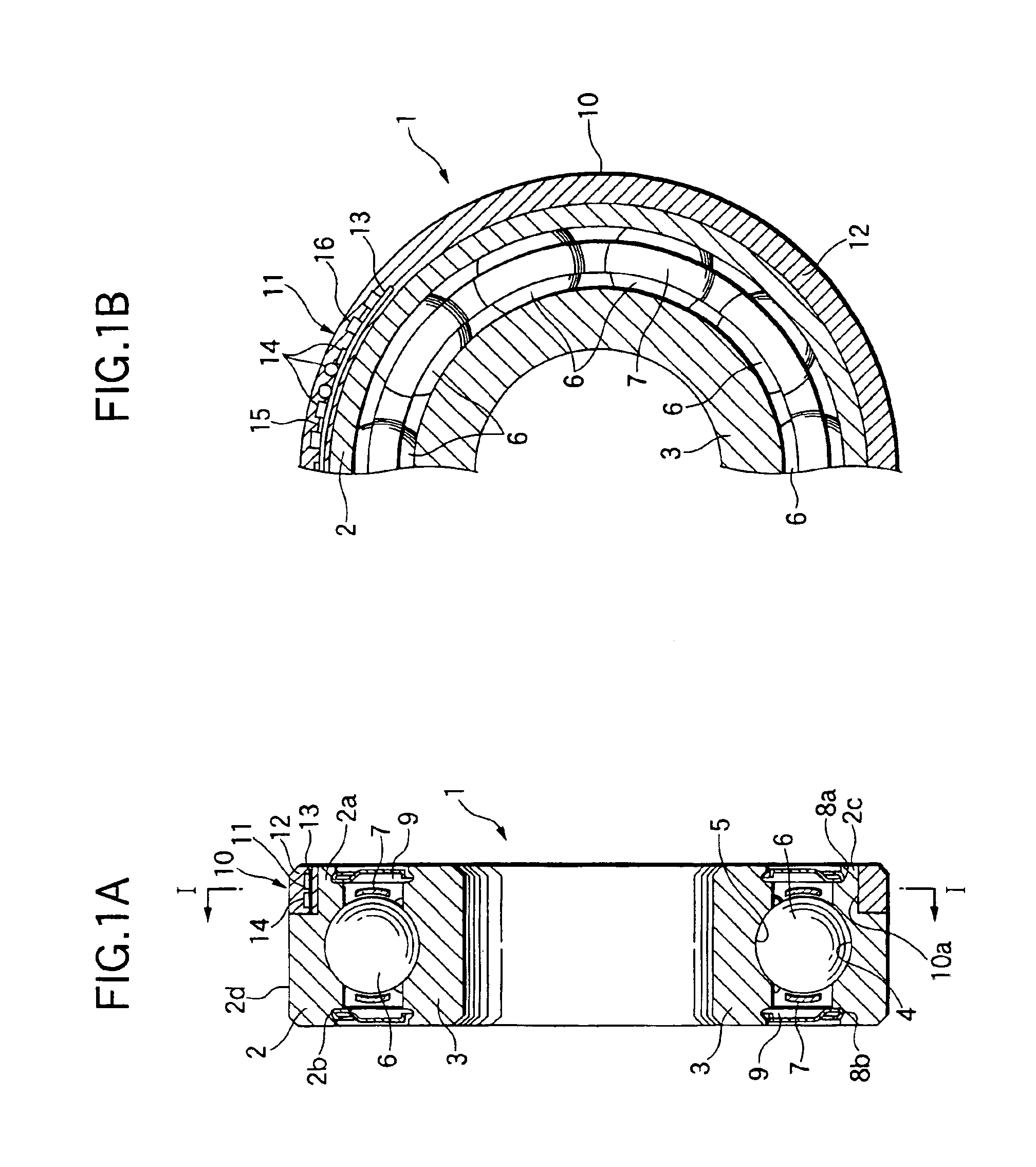
[0074]the invention will be described with reference to FIG. 2. In the bearing 21 as shown in FIG. 2, an annular groove 24 is formed entirely over the inner peripheral surface of an inner ring 23, viz., the annular groove is not formed in the outer ring 22. A sensor 11 is circumferentially disposed on the bottom surface 24a of the annular groove 24 in a state that the sensor 11 is located inside a prolongation of the side face 23a of the inner ring 23, but outside a prolongation of the inner peripheral surface 23b. The sensor 11 is molded by using an insulating material, e.g., a synthetic resin 12. The protecting synthetic resin 12 fills the annular groove 24, and is annular in shape. Incidentally, the synthetic resin 12 is provided for improving the performances of the dust-proof, water-proof and oil-proof. The end face and the inner peripheral surface of it are flush with the side face 23a and the inner peripheral surface 23b, while being continuous to the latter. To measure a tem...

fifth embodiment

[0081]the invention will be described with reference to FIG. 5. A bearing 51 shown in FIG. 5 includes a surface-opposed generator 52, which is located between the outer ring 2 and the inner ring 3. The surface-opposed generator 52 includes a coil 53 and a magnet 54. A shield 9 is fitted into a groove 8a, which is formed in the inner peripheral surface in an end 2a of the outer ring 2 in the widthwise direction, and corresponds to the location of the annular groove 10. And, the coil 53 is mounted on the inner side (=surface facing balls 6) of the shield 9. The magnet 54 is mounted on a holding plate 55, while being disposed in association with the coil 53. The holding plate 55 is fitted into a holding-plate mounting groove 56, which is formed in the outer peripheral surface of an end 3a of the inner ring 3 in the width direction.

[0082]The generator 52 generates electricity and supplies it to the sensor 11. The remaining portion of the embodiment is substantially the same as the corre...


PUM


Abstract

A rolling bearing with sensor includes an inner ring, an outer ring, a plurality of rolling elements disposed between the inner and outer rings, and a sensor having a detecting part detecting a state of the rolling bearing and a circuit part connected to the detecting part. The detecting part and the circuit part are attached to the rolling bearing.

Description

BACKGROUND OF THE INVENTION[0001]1. Field of the Invention[0002]The present invention relates to a rolling bearing device having a sensor for detecting vibration (acceleration), temperature, rotational speed, humidity (moisture) and the like, and a ring with the sensor for used with the rolling bearing device.[0003]2. Description of the Related Art[0004]The rolling bearings, which are used for reducing rotation resistance, have been used in various fields, such as industrial equipment, vehicles, airplanes, and power plants. The rolling bearing will be vibrated when the rotating shaft is eccentric and be heated through the rotation friction. The vibration and temperature will adversely affect the lifetime of the bearing. In some of industrial machines, a water-soluble cutting lubricant is frequently used in machining work. Accordingly, sometimes the bearing part receives a splash of it, which contains water. When the rolling bearing is mounted on a machine used outdoors, such an auto...

Claims


Application Information

Patent Timeline
Patent Type & Authority Patents(United States)
IPC IPC(8): G01P3/42G01P3/44F16C19/52F16C33/58
CPCF16C19/525F16C19/527F16C41/004F16C41/007F16C41/008F16C43/04G01P3/443F16C33/586F16C19/06F16C2226/30F16C2300/02
Inventor TAKIZAWA, TAKESHIENDO, SHIGERUMORITA, KOUICHISHODA, YOSHIOFUKUYAMA, HIROMASATAKAHASHI, TOSHIO
Owner NSK LTD
Why Eureka
Try Eureka