
Image processing device

a processing device and image technology, applied in the direction of thin material processing, instruments, printing, etc., can solve the problems of high manufacturing cost, cumbersome device overall structure, unfavorable use of separate drive sources for the rotation of each of these two platen rollers, etc., and achieve the effect of reducing the manufacturing cost of the devi

Inactive Publication Date: 2005-09-27
ROHM CO LTD
View PDF7 Cites 20 Cited by
  • Summary
  • Abstract
  • Description
  • Claims
  • Application Information

AI Technical Summary

Benefits of technology

[0008]It is therefore an object of the present invention to simplify the construction of the mechanism for rotating the original-document platen roller P1 and recording-paper platen roller P2 and thus reduce manufacturing costs thereof.
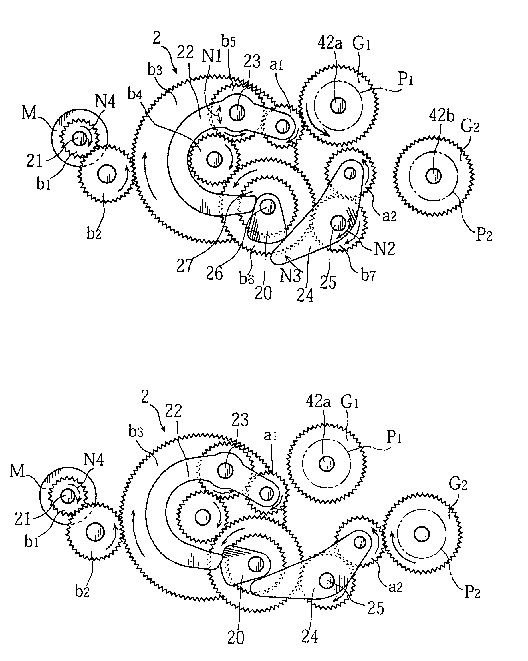
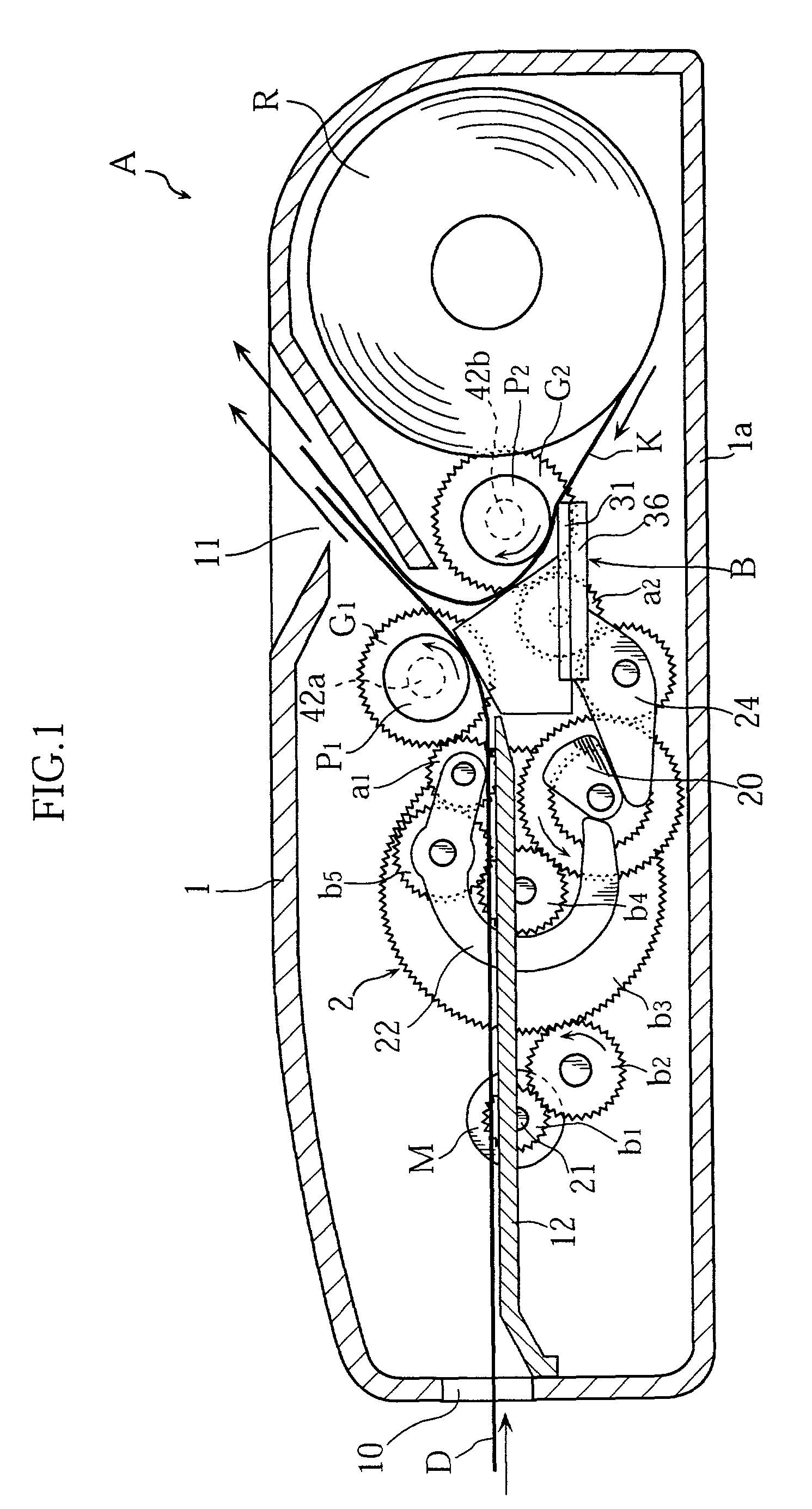
[0010]In the present invention, the two movable gears of the drive mechanism are provided so as to be capable of engaging directly with the original-document platen roller and recording-paper platen roller, not as intermediate gears of the drive mechanism but as distal gears thereof. According to such a constitution, the motive power transmission path of the drive mechanism is not obstructed at any point therealong due to the displacement of the two movable gears, meaning that a mechanism that permits displacement of the two movable gears can be constructed inside the drive mechanism in such a manner that substantially the entire capacity of the drive mechanism is utilized. In other words, in order to achieve the transmission of motive power to the two platen rollers and displacement of the two movable gears, a common motor, gears and other components can be utilized. Further, since the first movable gear and second movable gear are provided so as to be capable of engaging directly with the original-document platen roller and recording-paper platen roller respectively, it is not necessary to provide a multiplicity of gears therebetween as has been the case conventionally. The overall construction of the device is therefore simple and the total number of gears required by the device is small, which in turn permits a reduction in the manufacturing costs thereof.
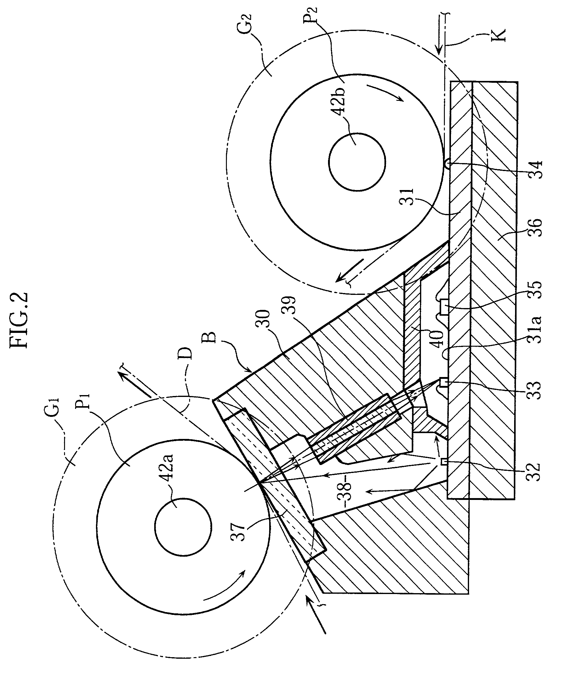
[0011]A preferred embodiment of the present invention further comprises an image read / write integrated head in which a plurality of photoreceptors for reading an original-document image, and a plurality of printing elements for performing image printing are mounted on the same side of the same base plate. The original-document platen roller is provided facing the plurality of photoreceptors, and the recording-paper platen roller is provided facing the plurality of printing elements. With a constitution of this kind, the original-document platen roller and recording-paper platen roller can be provided close to one another. Consequently, due to the narrowing of the interval between the two movable gears of the drive mechanism, miniaturization of the drive mechanism itself and simplification of the construction thereof are possible.
[0016]The switching mechanism preferably comprises a cam that has a cam gear for receiving drive force from the drive source; a first arm that is provided so as to be capable of coming into contact with the cam and on which the first movable gear is mounted; a second arm that is provided so as to be capable of coming into contact with the cam and on which the second movable gear is mounted. The cam establishes the position of the first movable gear and second movable gear through contact with the first arm and the second arm. With a constitution of this kind, by causing the cam to rotate, it is possible to change the position of the first movable gear and second movable gear via the first arm and the second arm, respectively.
[0020]The drive source is preferably a motor that has a drive shaft capable of forward and reverse rotation, and the switching mechanism causes the cam to rotate, without transmitting drive force of the motor to the cam gear during forward rotation of the drive shaft, or transmitting the drive force to the cam gear during reverse rotation of the drive shaft. With a constitution of this kind, it is possible for a single, rotating motor to perform not only the rotational movement of the original-document platen roller and recording-paper platen roller, but also movement to change the position of the two movable gears by means of a rotational movement by the cam. This obviates the need to further provide a dedicated motor for changing the position of the two movable gears, and the overall construction of the image processing device is thereby simplified.
[0023]According to the present invention, a single motor generates drive force for the rotation of the original-document platen roller and recording-paper platen roller, and for changing the position of the two gears. As a result, the image processing device of the present invention does not need to comprise individual motors for such movements, and the manufacturing costs thereof can thus be reduced.

Problems solved by technology

The use of separate drive sources for the rotation of each of these two platen rollers is unfavorable on account of the high costs involved.
However, this has resulted in a cumbersome overall constitution of the device and high manufacturing costs.

Method used


Image

  • Image processing device
  • Image processing device
  • Image processing device

Examples


case 30

[0036]Case 30 is provided on base plate 31 so as to cover the plurality of light sources 32, plurality of photoreceptors 33 and plurality of drive ICs 35, but not the plurality of heating elements 34. Case 30 comprises, on the upper face thereof, a transparent plate 37 that is light-transmissive, and original-document platen roller P1 is provided facing the surface of this transparent plate 37. Meanwhile, recording-paper platen roller P2 is provided facing the plurality of heating elements 34 that are in a row shape and exposed on base plate 31. Original-document platen roller P1 and recording-paper platen roller P2 have shaft portions 42a, 42b respectively provided at both ends of each of these respective platen rollers. These shaft portions 42a, 42b are supported by members (not shown) that are fixed with respect to case unit 1. Consequently, original-document platen roller P1 and recording-paper platen roller P2 can rotate in a set position. Driven gear G1 and G2 are respectively...


PUM


Abstract

The image processing device (A) comprises an original-document platen roller (P1) that has a first driven gear (G1) and is for transporting an original document (D), a recording-paper platen roller (P2) that has a second driven gear (G2) and is for transporting recording paper (K), and a drive mechanism (2) that has a first movable gear (a1), a second movable gear (a2), and a drive source (M) and is for transmitting a drive force generated by this drive source (M) to the first driven gear (G1) and second driven gear (G2). First movable gear (a1) is provided so as to be capable of engaging directly with first driven gear (G1), and second movable gear (a2) is provided so as to be capable of engaging directly with second driven gear (G2).

Description

TECHNICAL FIELD[0001]The present invention relates to an image processing device, more particularly to an image processing device that comprises an original-document platen roller that is for transporting an original document, and a recording-paper platen roller that is for transporting recording paper.BACKGROUND ART[0002]An image processing device that is capable of performing image-read processing and image-print processing, such as a facsimile device, for example, typically comprises two types of platen roller. One such platen roller is an original-document platen roller that is for transporting an original document that has an image to be read, and that is actuated when image-read processing takes place. The other platen roller is a recording-paper platen roller that is for transporting recording paper which is to be subjected to print-processing, and that is actuated when image-print processing takes place. The use of separate drive sources for the rotation of each of these two...

Claims


Application Information

Patent Timeline
Patent Type & Authority Patents(United States)
IPC IPC(8): H04N1/12H04N1/00B65H5/06H04N1/04H04N1/31
CPCH04N1/02427H04N1/02463H04N1/1215H04N1/193
Inventor ONISHI, HIROAKIFUJIMOTO, HISAYOSHI
Owner ROHM CO LTD
Learn More