
Wastewater treatment apparatus and system

a wastewater treatment apparatus and wastewater technology, applied in the direction of liquid displacement, other chemical processes, separation processes, etc., can solve the problems of slow and inefficient separation and anaerobic degradation of solids, inconvenient discharge to surface waterways, and effluent from the outlet of a septic tank

Inactive Publication Date: 2005-09-27
SMITH DANNY R
View PDF32 Cites 9 Cited by
  • Summary
  • Abstract
  • Description
  • Claims
  • Application Information

AI Technical Summary

Problems solved by technology

The separation and anaerobic degradation of the solids is, however, slow and inefficient.
As a result, the liquid effluent from the outlet of a septic tank still contains dissolved and suspended pollutants, odors and possible pathogens, and is not suitable to discharge to a surface waterway.
However, this subsoil treatment encourages and promotes the growth of bacteria in the subsoil, which over time results in a slime filling and blocking the pores and interstitial spaces of the subsoil.
When this occurs, the subsoil is no longer permeable and the septic system can no longer function properly.
As the drainage fields in existing septic systems fail, the lack of suitable soil and more stringent water pollution control regulations proscribe the installation of another drainage field.
However, at present, a switch to an aerobic treatment system requires the installation of a complete, new system and abandonment of the septic tank as well as the drainage field of the failed anaerobic system.

Method used


Image

  • Wastewater treatment apparatus and system
  • Wastewater treatment apparatus and system
  • Wastewater treatment apparatus and system

Examples


Embodiment Construction

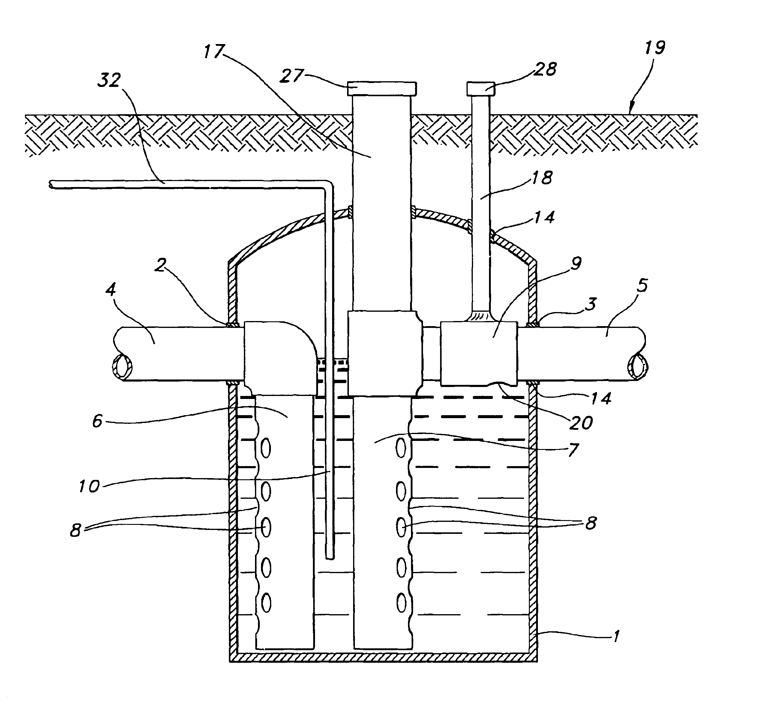
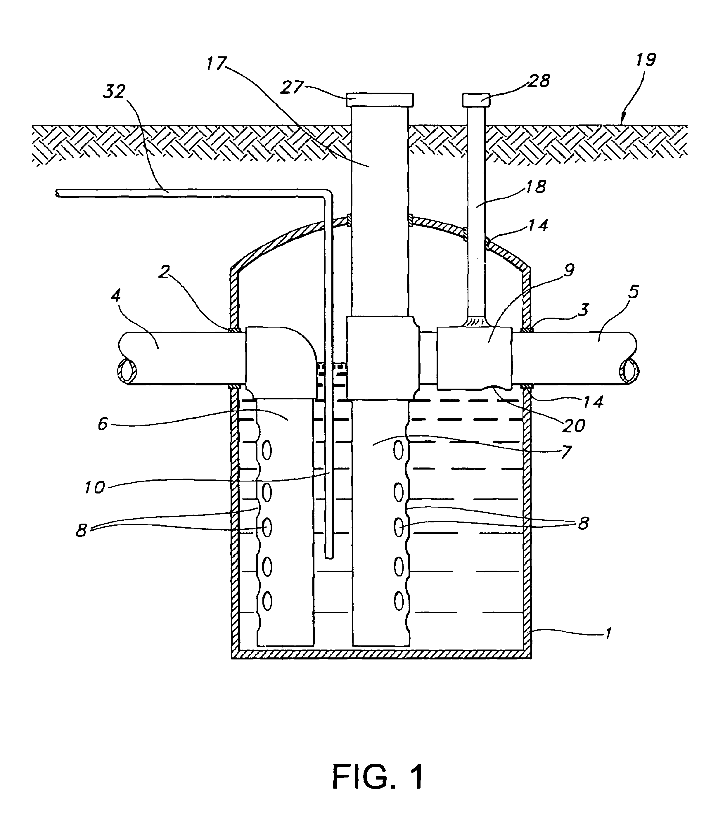
[0019]As shown in FIG. 1, the invention disclosed herein comprises a chlorinating treatment tank for further treating domestic wastewater is disclosed. The chlorinating treatment tank is comprised of a tank 1, with cylindrical vertical sides, a closed bottom and a closed top. In the preferred embodiment, the tank is comprised of a 55-gallon polyethylene drum, fabricated with side and bottom as a single unit, and having a removable top held in place by a lever clamp.

[0020]Disposed within the side of the tank 1 are an inlet port 2 and an outlet port 3. These ports 2, 3 may be holes or apertures cut or bored into the tank side. The two ports 2, 3 are disposed opposite each other and at the same level in the side of the tank 1. The ports 2, 3 are posited proximate the top edge of the tank 1, without denigrating the mechanical integrity of the tank 1.

[0021]Registering with the inlet port 2 and outlet port 3 are an effluent inlet pipe 4 and an effluent outlet pipe 5, respectively. Elastom...


PUM

PropertyMeasurementUnit
volumeaaaaaaaaaa
length of timeaaaaaaaaaa
residence timeaaaaaaaaaa

Abstract

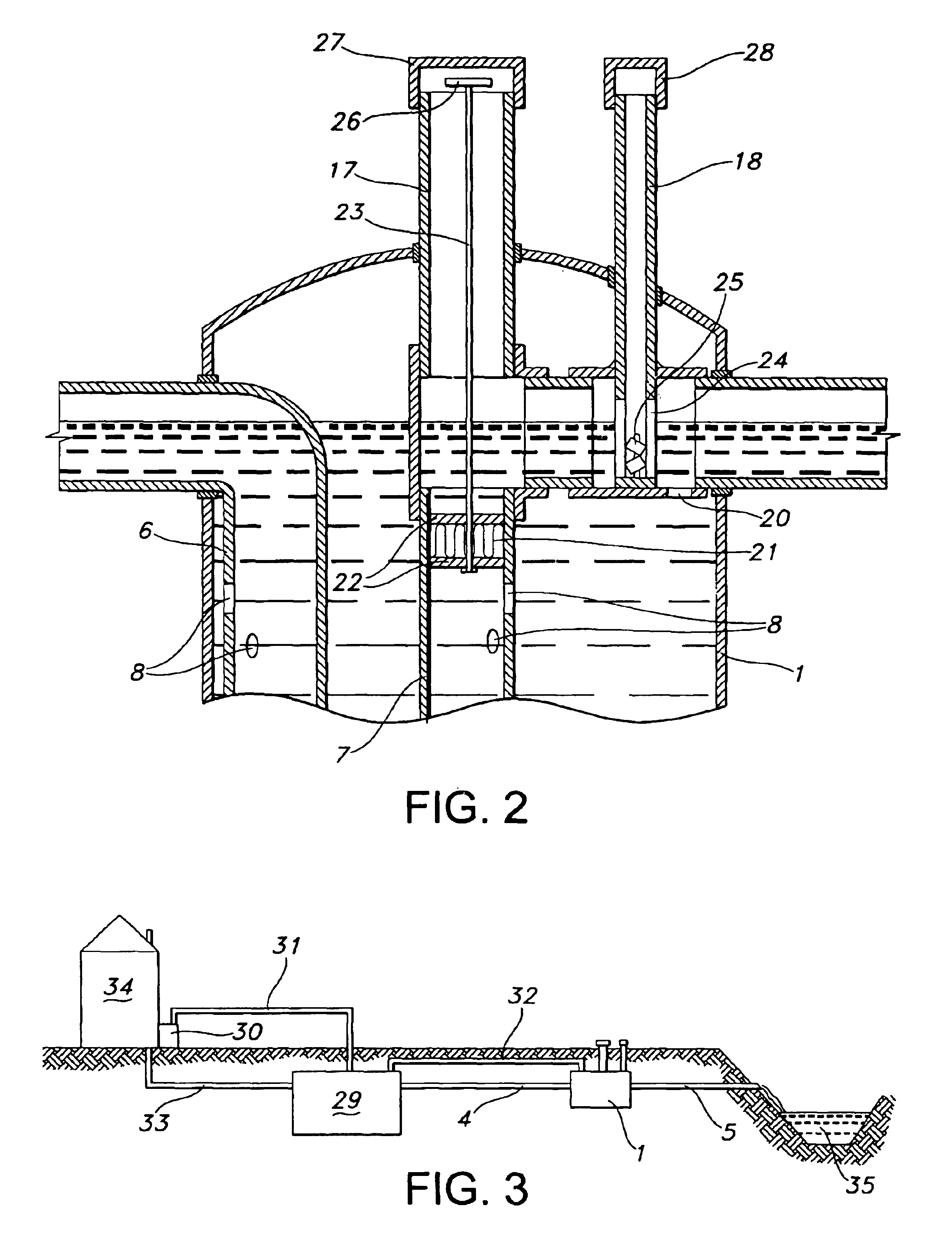
An apparatus and system are disclosed for retrofitting a septic tank from a failed residential wastewater treatment system to permit discharge to a surface water body rather than an underground drainage field. The apparatus is a chlorinating tank, comprised of a tank having an inlet and outlet pipe. An inlet diffuser and an outlet diffuser are posited within the chlorinating tank, the inlet diffuser is in hydraulic communication with the inlet pipe, and the outlet diffuser is in hydraulic communication with the outlet pipe. A filter is posited in the outlet diffuser for filtering any remaining solids in the treated wastewater. A chlorinating device is posited downstream of the filter within the chlorinating tank, for adding dissolved chlorine to the chlorinating tank volume.The system for treating domestic wastewater utilizing a failed septic system is comprised of a source of pressurized air, a sparger for sparging the pressurized air into the waste water contents of the septic tank, a chlorinating tank, comprised of means for mixing the partially treated wastewater, a filter and a chlorinating device, and a vent line for routing and treating noxious vent gases from the septic tank into the chlorinating tank. A discharge pipe is further provided for discharging the treated wastewater from the chlorinating tank to a surface waterway.

Description

BACKGROUND OF THE INVENTION[0001]1. Field of the Invention[0002]The invention disclosed herein relates to an apparatus, system and method for treating domestic wastewater and sewage.[0003]2. Description of Prior Art[0004]Residential dwellings are constructed with various systems to be fit for human habitation, including some means for disposing of sewage and wastewater produced by the dwelling's inhabitants. Dwellings located in urban or municipal areas are usually connected to a network of sewer pipelines, which route wastes to a central treatment works. Dwellings in rural areas, on the other hand, usually have some form of partial or full treatment system located on site. These on-site treatment systems include anaerobic treatment systems, such as cesspools or septic tanks, and aerobic systems, such as aerated treatment tanks.[0005]Anaerobic treatment systems treat domestic waste and waste water using anaerobic, or “without oxygenbacteria. The septic tanks used in such systems a...

Claims


Application Information

Patent Timeline
Patent Type & Authority Patents(United States)
IPC IPC(8): C02F1/68C02F1/76C02F3/28
CPCC02F1/688C02F3/28C02F1/001C02F1/76
Inventor SMITH, DANNY R.
Owner SMITH DANNY R
Learn More