Vulcanizing mold for pneumatic tires

a technology of pneumatic tires and molds, which is applied in the field of vulcanizing molds and vulcanizing methods of pneumatic tires, can solve the problems of uneven rubber material flow, defect formation in the tread land region, nicks and/or cracks, etc., and achieve the effect of preventing reducing the flow of rubber material, and free from unevenness

Inactive Publication Date: 2005-09-27
BRIDGESTONE CORP
View PDF9 Cites 13 Cited by
  • Summary
  • Abstract
  • Description
  • Claims
  • Application Information

AI Technical Summary

Benefits of technology

[0009]It is a more specific object of the present invention to provide improved vulcanizing method and mold therefor, which effectively prevent formation of defects in the tread land regions of tires when the mold is opened.
[0020]In the method according to the present invention, the formation at the side portions of a green tire is performed before the formation at the tread portion of the green tire, by means of the sidewall mold members have forming inner surfaces which are substantially free from unevenness. It is thus possible to significantly reduce the flow of the rubber material due to the formation, effectively preventing the flow of the rubber material into a space, if any, between the sidewall mold members and the segments on their radially outer sides. As a result, it is possible to advantageously prevent the rubber material from biting between the sidewall mold members and the segments which are being displaced radially inwards, for performing subsequent formation at the tread portion of the green tire.

Problems solved by technology

However, upon removal of a product tire out of the mold after completion of vulcanization, the mold is opened only by a relative vertical displacement of the upper and lower mold halves, and the full-type mold may thereby give rise to formation of defective products depending upon the tread pattern.
More particularly, during the relative vertical displacement of the mold halves, the projections or ridges provided on the mold inner surface for forming the tread portion of the tire may exert excessive shearing forces to the tread land regions, thereby causing such problem that defects tend to be formed in the tread land regions such as nicks and / or cracks.
This is particularly the case where tires having a large aspect ratio are to be produced, such as off-road tires and motorcycle tire, because the size of the mold, hence the size of vulcanizing machine, must be large with reference to the tire size, thereby resulting in increased cost for the entire facility.

Method used


Image

  • Vulcanizing mold for pneumatic tires
  • Vulcanizing mold for pneumatic tires
  • Vulcanizing mold for pneumatic tires

Examples


Embodiment Construction

[0026]The present invention will be further described hereinafter with reference to a preferred embodiment shown in the accompanying drawings.

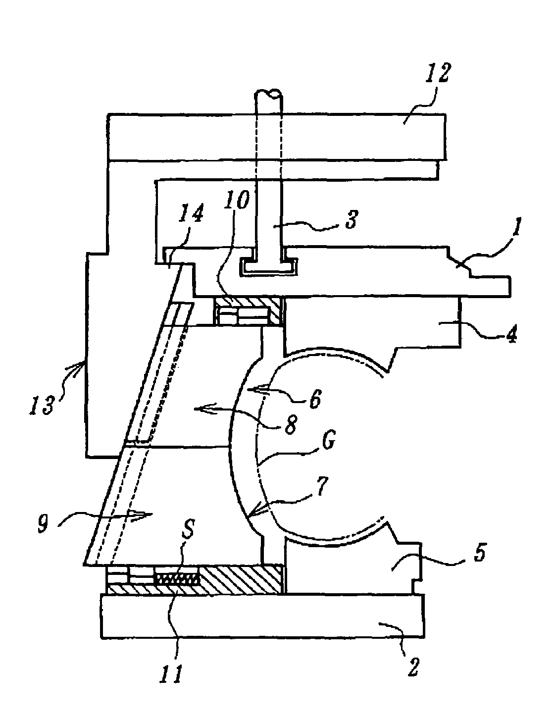
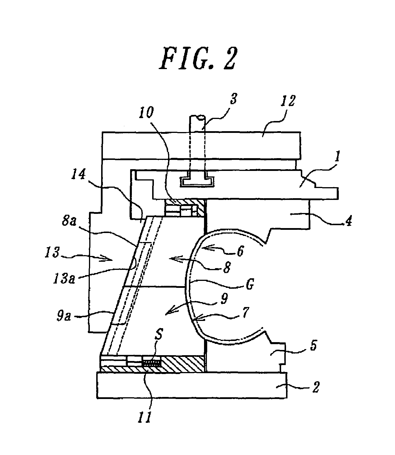
[0027]FIG. 2 is a longitudinal sectional view of an essential part of an embodiment of the present invention, wherein reference numerals 1 and 2 designate upper base plate and lower base plate, respectively. Here, the upper base plate 1 can be displaced vertically upwards and downwards relative to the lower base plate 2 also acting as a lower platen, under the operation of a cylinder rod 3 of a cylinder device (not shown).

[0028]Upper and lower sidewall mold members 4, 5 which contribute to the formation of the outer surfaces of tire sidewall portions are provided by directly fixing them to the upper and lower base plates 1, 2, respectively. There are also provided upper and lower tread mold members 6, 7 which contribute to the formation of the tire tread surface, on the outer peripheral sides of the sidewall mold members 4, 5, respectively. He...


PUM

PropertyMeasurementUnit
sizeaaaaaaaaaa
shearing forcesaaaaaaaaaa
diameteraaaaaaaaaa

Abstract

A vulcanizing mold for pneumatic tires includes upper and lower base plates, upper and lower sidewall mold members attached to the upper and lower base plates, respectively; and upper and lower tread mold members attached to the upper and lower base plates, respectively. The upper and lower tread mold members are constituted of upper segments and lower segments, respectively. The upper and lower segments can be radially expanded and contracted relative to the upper and lower sidewall mold members, respectively. In operation, the upper and lower sidewall mold members are displaced toward each other so that the upper and lower segments are brought into abutment with each other. Then, a single cam ring is operated to cause all of the segments to be simultaneously displaced radially inwards and relative to the upper and lower sidewall mold members, with the upper segments in abutment with the lower segments.

Description

BACKGROUND OF THE INVENTION[0001]1. Field of the Invention[0002]The present invention relates to a vulcanizing mold and vulcanizing method for pneumatic tires.[0003]2. Description of the Related Art[0004]Conventional vulcanizing molds for pneumatic tires are typically classified into two types, i.e., a full-type mold and a split-type mold. A full-type mold has inner surface portions for forming the tread portion and side portions of a tire, and is divided into upper and lower mold halves at a parting plane which corresponds to the tire equatorial plane. These mold halves are displaceable in the vertical direction toward and away from each other for closing and opening the mold, respectively.[0005]The full-type mold is advantageous in that it is simple in structure, small in size and inexpensive. However, upon removal of a product tire out of the mold after completion of vulcanization, the mold is opened only by a relative vertical displacement of the upper and lower mold halves, and...

Claims


Application Information

Patent Timeline
Patent Type & Authority Patents(United States)
IPC IPC(8): B29C33/02B29C35/02B29D30/06B29K21/00B29K105/24B29L30/00
CPCB29D30/0629B29D2030/063
Inventor KATA, TAKEHIROMIURA, MASARU
Owner BRIDGESTONE CORP
Why Eureka
Try Eureka