
Atmospheric pressure ion source

a technology of atmospheric pressure and ion source, which is applied in the direction of optical radiation measurement, separation process, instruments, etc., can solve the problems of electrode degradation, loss of analyte ions sensitivity, and difficulty in maintaining discharg

Active Publication Date: 2005-09-27
JEOL USA
View PDF6 Cites 130 Cited by
  • Summary
  • Abstract
  • Description
  • Claims
  • Application Information

AI Technical Summary

Benefits of technology

"The invention is an atmospheric pressure ionization source that can produce both positive and negative ions for use in various instruments. The source has three chambers, two of which are connected, and an optional third chamber. The first chamber has a port for carrier gas and a port for a lens electrode. The second chamber has a port for a portable conductive grid. The third chamber has a port for carrier gas and an optional lens electrode. The source can switch between positive and negative ion modes without changing the potentials on the electrodes. The source can be used in a \"sniffer\" mode where the analyte is cooled by the reactive species. The invention allows for the analysis of analytes in the positive or negative ion mode."

Problems solved by technology

1. The presence of oxygen or other contaminants in the air leads to degradation of the electrodes.
2. It can be difficult to maintain the discharge in the presence of contaminants, requiring a high electrical potential or pulsed potentials.
3. A corona discharge in air leads to the formation of species, such as NO2−, NO3−, and related cluster ions. These ions can cause a loss of sensitivity for analyte ions (C. A. Hill and C. L. P. Thomas, Analyst, 2003, 128, pp. 55-60) and can interfere with the detection of NO2− and NO3− produced from analytes containing nitro functional groups, such as nitro explosives or in the case of chloride ion interference with chlorate propellants and rocket motors or phosphate interference with chemical warfare-related compounds.
4. Introducing air and analyte into the discharge region limits the possibilities for controlling the nature of the chemical background to control the ion-formation chemistry.
The device described requires substantially reduced pressures and does not describe means for using metastable atoms for atmospheric pressure ionization mass spectrometry or ion mobility spectrometers.

Method used


Image

  • Atmospheric pressure ion source
  • Atmospheric pressure ion source
  • Atmospheric pressure ion source

Examples


Embodiment Construction

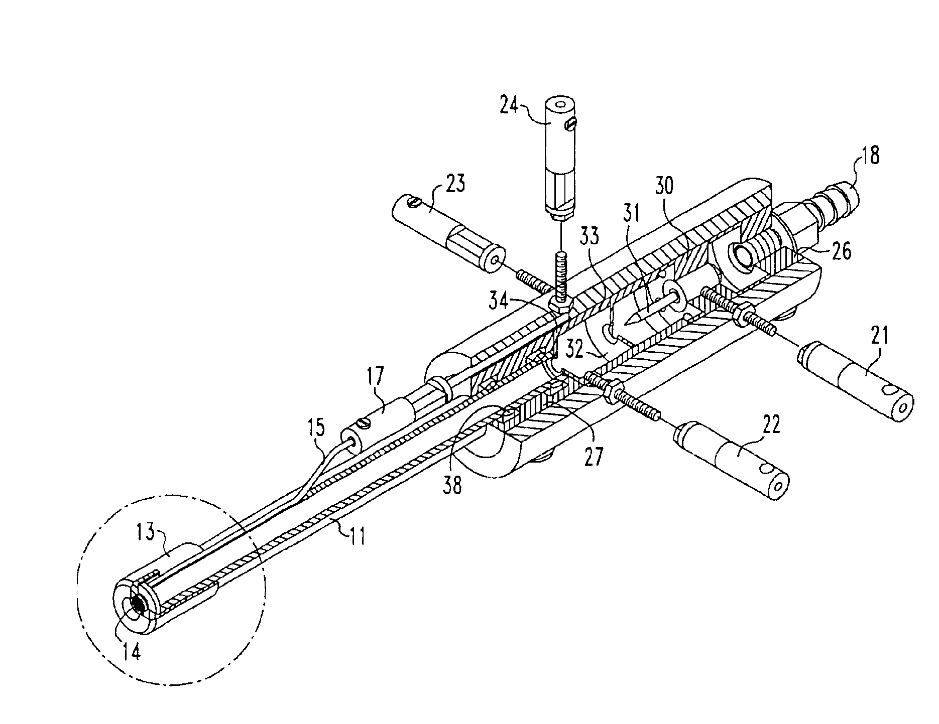
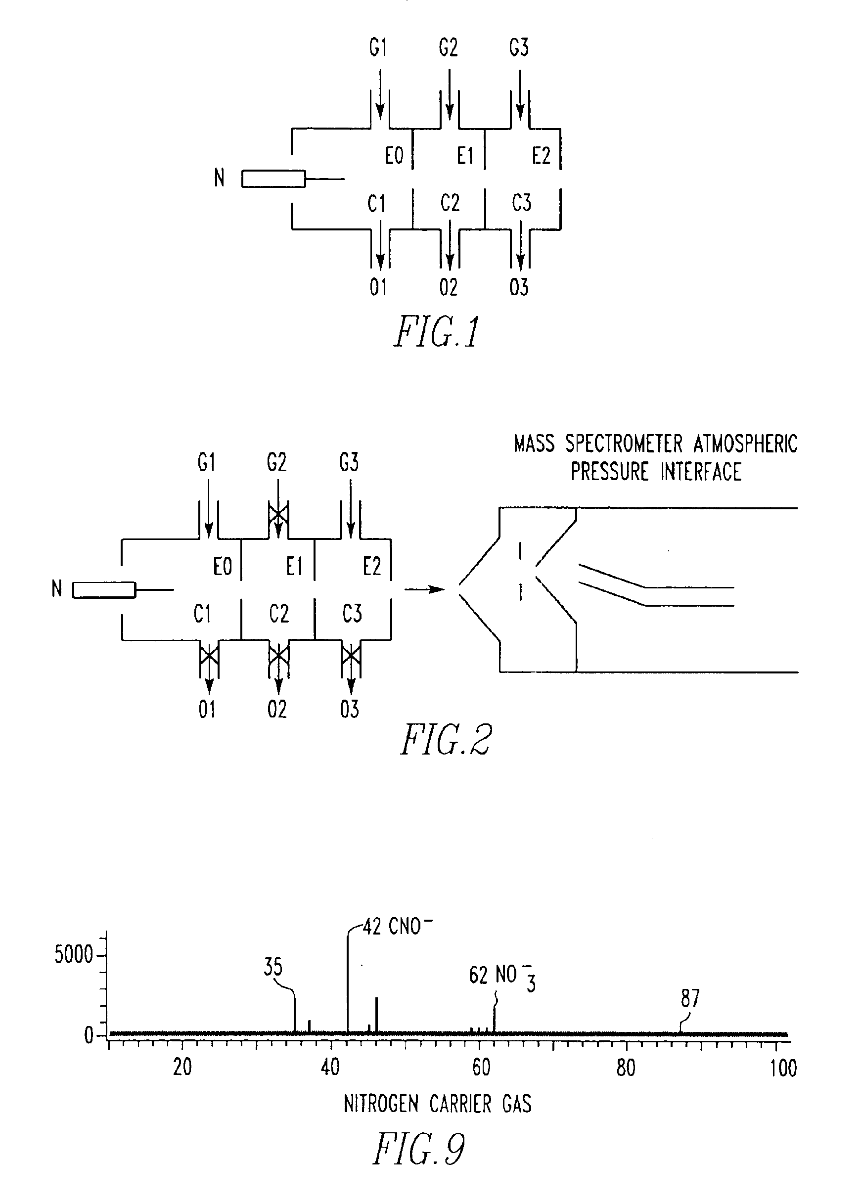
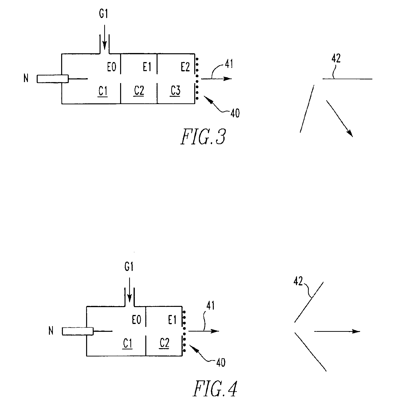
[0049]A generalized implementation of the present invention is shown schematically in FIG. 1. This device provides an electrode N, for example, a needle electrode, to which an electrical potential can be applied in a first atmospheric pressure chamber C1 into which a carrier gas can be introduced through gas inlet G1 and flow out of a gas-closeable outlet O1. The electrode N may be a point, line, plane, or curved-shape electrode. A needle electrode is an example of a point electrode, and a trim blade is an example of a line electrode. Indeed, there may be multiple needles or other electrodes of the same polarity in the first atmospheric chamber, an arrangement especially useful for chemical agent monitors. A corresponding increase in detection sensitivity is observed when multiple electrodes (N) are used. The counter-electrode E0 contains a hole through which gas and charged particles can pass. It is set to a potential (for example, ground potential) that allows a corona or glow ele...


PUM

PropertyMeasurementUnit
pressuresaaaaaaaaaa
pressuresaaaaaaaaaa
volumeaaaaaaaaaa

Abstract

A non-radioactive atmospheric pressure device for ionization of analytes comprises an atmospheric pressure chamber having an inlet for carrier gas, a first electrode at one end, and a counter-electrode at the other end of the chamber for creating an electrical discharge in the carrier gas thus creating metastable neutral excited-state species. Optionally, a grid is provided to generate electrons or ions by contact with the excited-state species. The carrier gas containing the excited-state species or the electrons generated therefrom is directed at an analyte at atmospheric pressure near ground potential to form analyte ions.

Description

CROSS REFERENCE TO RELATED APPLICATION[0001]This application discloses subject matter disclosed in Provisional Patent Application No. 60 / 460,179, filed Apr. 14, 2003, and the benefits of 35 U.S.C. § 119(e) are claimed.BACKGROUND OF THE INVENTION[0002]1. Field of the Invention[0003]This invention relates to atmospheric ionization of analytes with metastable atoms and molecules. Metastable atoms and molecules (M*) are excited-state species with long lifetimes. Metastable species are produced in corona or glow electrical discharges. Other methods of producing excited-state species include electron impact, photoionization, and controlled interaction of high energy particles with a reactant species. Collisions between excited-state species and ground-state species can result in ionization of the ground-state species and release of electrons by a process known as Penning ionization, for example:M*+N−>N++M+e−  Equation 1[0004]2. Description of Related Art[0005]Regulatory and safety issu...

Claims


Application Information

Patent Timeline
Patent Type & Authority Patents(United States)
IPC IPC(8): G01N24/00H01J49/10H01J49/00B01DG01N27/64H01J49/14H01J49/40
CPCG01N27/622H01J49/14H05H1/24H01J49/0459H01J49/10H05H1/34H05H1/3447H05H1/47G01N27/623H01J49/147H01J49/00
Inventor CODY, ROBERT B.LARAMEE, JAMES A.
Owner JEOL USA
Learn More