Motor endshield assembly for an electronically commutated motor

a technology of electronic commutation and end shields, which is applied in the direction of windings, magnetic circuit rotating parts, magnetic circuit shapes/forms/construction, etc., can solve the problems of increasing costs, and achieve good thermal performance of the motor and dissipate heat from the power devices

Inactive Publication Date: 2005-09-27
GENERAL ELECTRIC CO
View PDF35 Cites 38 Cited by
  • Summary
  • Abstract
  • Description
  • Claims
  • Application Information

AI Technical Summary

Benefits of technology

[0011]With the above described endshield assembly, only one compartment is required since the electronic controls are located within the motor housing. In addition, use of the endshield as a low impedance path to dissipate heat from the power devices of the internal electronic circuitry to the ambient environment prov

Problems solved by technology

However, this increases costs since another compart

Method used


Image

  • Motor endshield assembly for an electronically commutated motor
  • Motor endshield assembly for an electronically commutated motor
  • Motor endshield assembly for an electronically commutated motor

Examples


Embodiment Construction

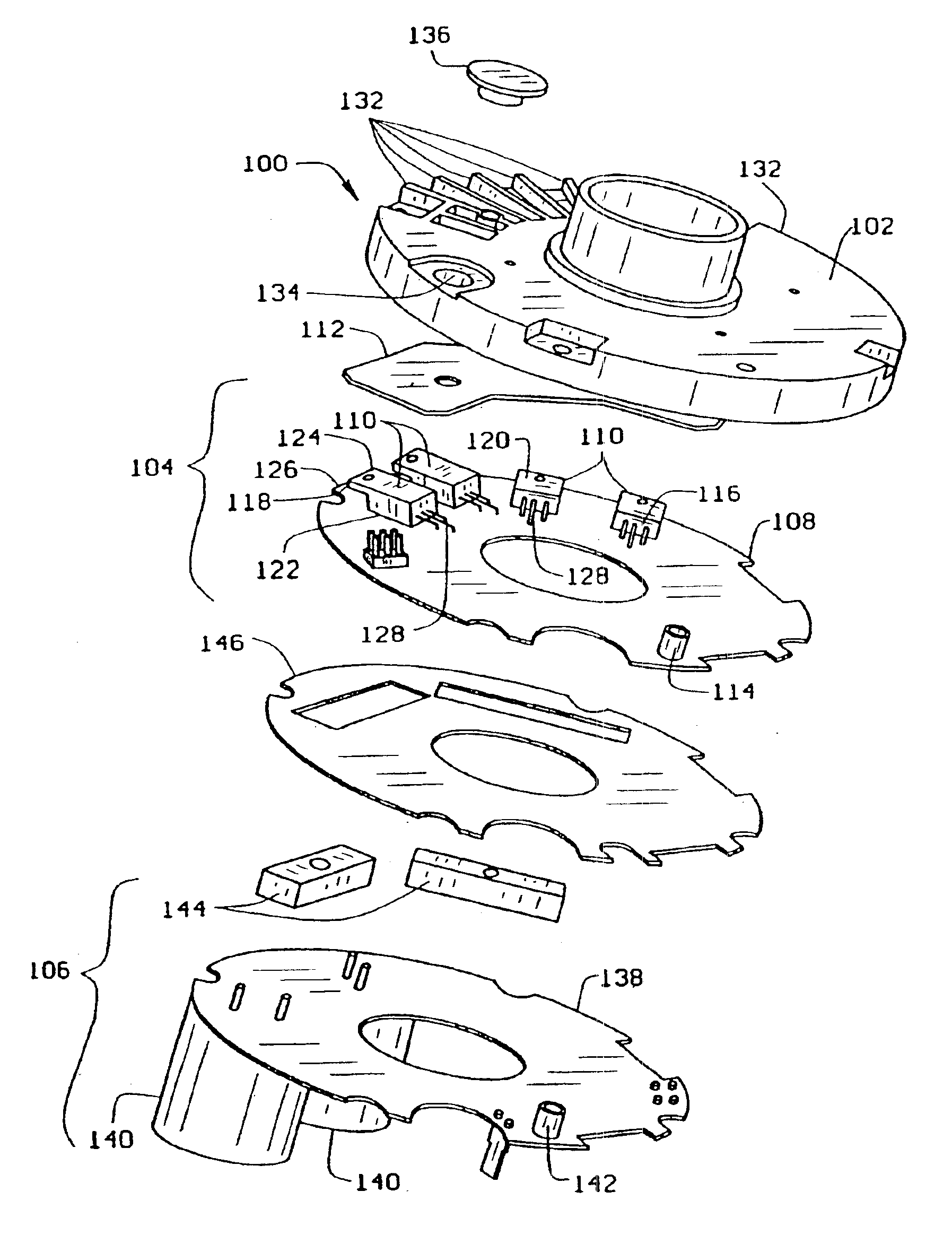
[0017]FIG. 1 is an exploded view of an endshield assembly 100 for an electronically commutated motor (not shown). Endshield assembly 100 includes an endshield 102, a control assembly 104, and a power assembly 106. Control assembly 104 includes a control board 108, a plurality of transistors 110, a thermal pad 112, and a spacer 114. In one embodiment, spacer 114 is fabricated from nylon and extends between control board 108 and endshield 102. Spacer 114 helps to maintain a predetermined separation distance between control board 108 and endshield 102.

[0018]Transistors 110 include a front 116, back 118, top 120, bottom 122, and a tab 124. Tab 124 extends from back 118 of transistors 110 and has a surface 126 that is an extension of, and is substantially parallel to, top 120. A plurality of leads 128 extend from front 116 of transistor 110. In one embodiment, leads 128 extend substantially parallel to control board 108 and maintain a substantially constant separation distance between th...


PUM


Abstract

An endshield assembly for an electronically commutated motor includes an endshield, a control assembly, and a power assembly. The endshield includes a plurality of recessed fins on an outer surface, and a substantially flat raised portion on an internal surface. The raised portion is in contact with a thermal pad. The control assembly includes the thermal pad and a control board on which is located a plurality of power transistors. The thermal pad provides thermal contact between the transistors and the endshield to enable the endshield to dissipate heat from the transistors. The transistors include a plurality of leads that extend substantially parallel to the control board which enable the leads to be coated for protection against harsh external environments. The power assembly includes a power board having an insulator positioned between the power board and the control board.

Description

[0001]This application is a 371 of PCT US99 / 14753 filed Jun. 29, 1999, which is a continuation of U.S. provisional Ser. No. 60 / 091,257 filed Jun. 30, 1998.BACKGROUND OF THE INVENTION[0002]This invention relates generally to electric motors and more particularly, to an endshield assembly for an electric motor.[0003]Known electronically commutated motors have a multi-stage winding assembly and a magnetic assembly associated for relative rotation. The winding stages of the multi-stage winding assembly have a preset energization sequence that includes at least one unenergized winding stage in which an induced back EMF appears. When integrated over time to a predetermined value, the induced back EMF indicates the instant at which the relative angular position between the multi-stage winding assembly and the magnetic assembly is suitable for the sequential commutation of the next winding stage.[0004]The electronic circuitry for an electronically commutated motor generally includes a power...

Claims


Application Information

Patent Timeline
IPC IPC(8): H02K5/00H02K5/20H02K11/04
CPCH02K11/0073H02K5/20H02K11/33H02K5/207
Inventor WRIGHT, KAMRON M.LYTLE, PETER B.YOUNG, ANDREW N.
Owner GENERAL ELECTRIC CO
Why Eureka
Try Eureka