Deflection yoke for cathode ray tube

Inactive Publication Date: 2005-09-27
SAMSUNG SDI CO LTD
View PDF12 Cites 3 Cited by
  • Summary
  • Abstract
  • Description
  • Claims
  • Application Information

AI Technical Summary

Benefits of technology

[0016]In one embodiment, the present invention provides a deflection yoke for a cathode ray tube that allows for the grinding of an inner surface of a ferrite core mounted to a deflection coi

Problems solved by technology

However, the ferrite core is formed by pressing iron oxide containing iron, zinc, manganese, copper, nickel, barium, yttrium, etc. in a mold, then sintering the resulting material in a furnace at a temperature of approximately 1,400° C. If the sintered material is used as is, an error results in the precision of its dimensions of roughly ±0.5 mm.
With the above grinding method, grinding may be performed on areas formed a

Method used


Image

  • Deflection yoke for cathode ray tube
  • Deflection yoke for cathode ray tube
  • Deflection yoke for cathode ray tube

Examples


Example

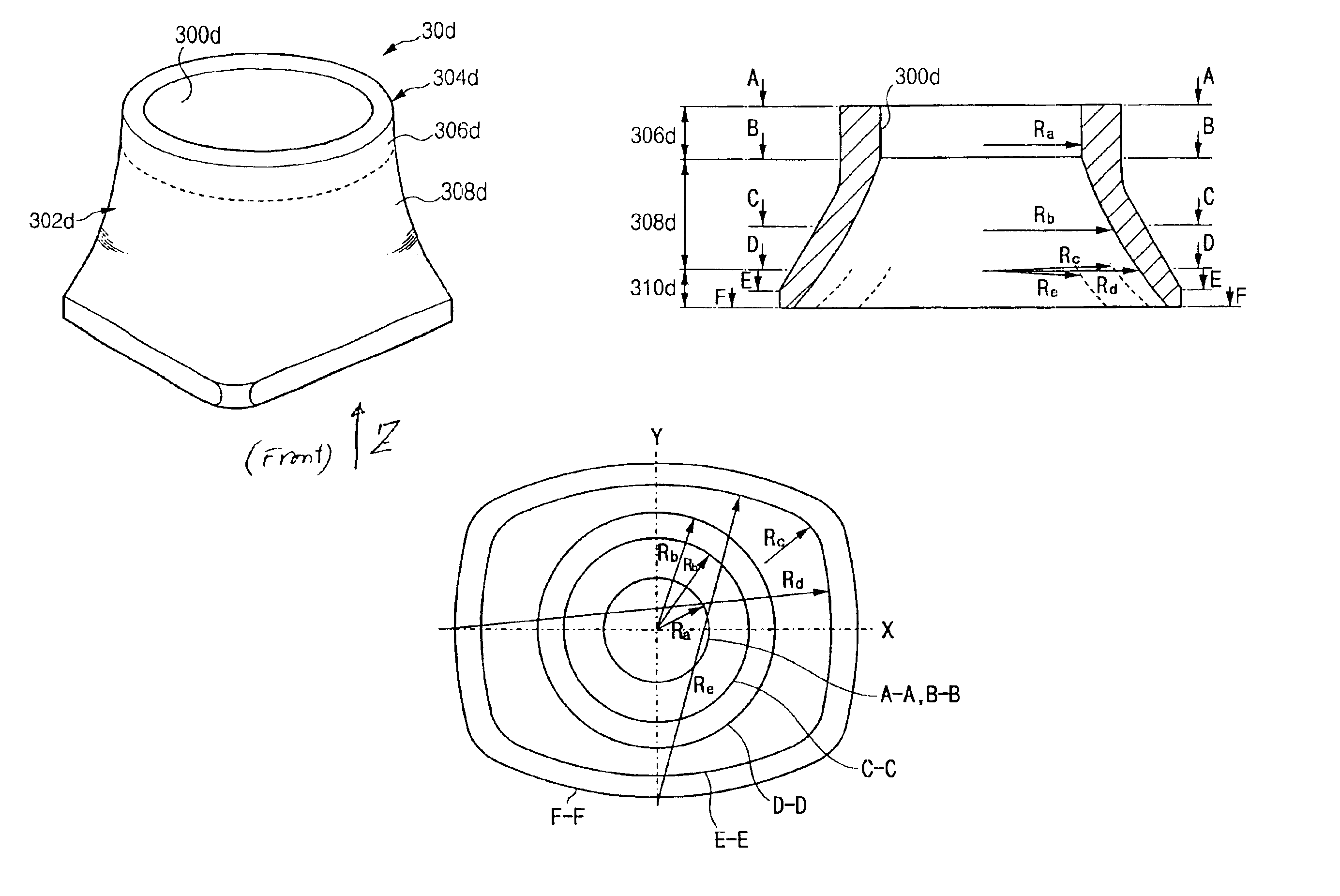
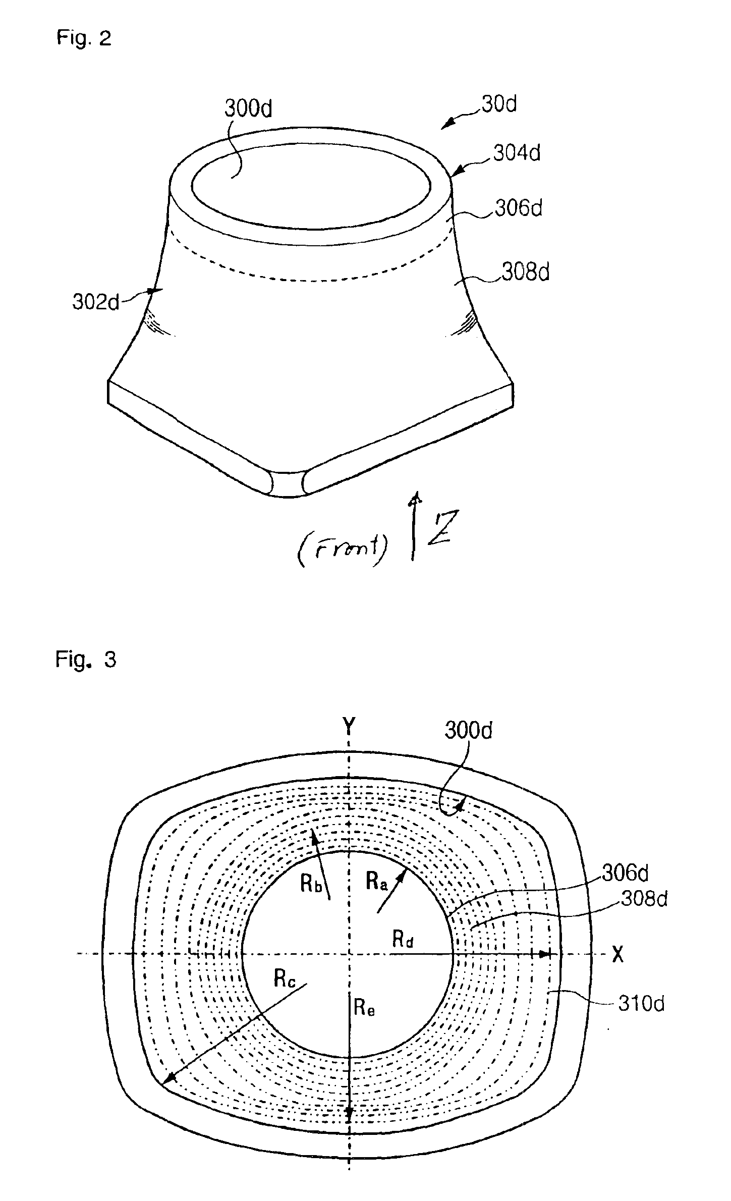
[0036]FIGS. 2-5 show the ferrite core 30d according to the first embodiment of the present invention.

[0037]Referring to FIG. 2, the ferrite core 30d of the deflection yoke 30 includes a body 304d having an inner surface 300d and an outer surface 302d. The inner surface 300d has three sections. The first section 306d has the shape of a section of a circle with a radius Ra that does not vary from one end to the other end of the first section. The second section 308d is connected to the first section 306d and has the shape of a circle with a radius Rb that varies from one end to the other end of the second section. The radius Rb increases going from the back to the front of the ferrite core 30d, along the inner surface 310d) The third section 310d is connected to the second section 308d and has a non-circular cross section inner surface, as shown in FIG. 3.

[0038]The third section 310d of the inner surface 300d has the shape of segments of three circles, each segment with different radi...

Example

[0056]In the second embodiment of the present invention, a ferrite core 60d is funnel-shaped and has an inner surface 600d and an outer surface 602d, similar to the same element of the first embodiment. The inner surface 600d includes a first section 604d realized through a circle having a varying radius, and a second section 606d having a non-circular cross section and connected to the first section 604d.

[0057]The first section 604d of the inner surface 600d corresponds to the second section in the first embodiment, and the second section 606d corresponds to the third section in the first embodiment. Since the structures of these elements and of their modified example(s) are identical to that described above, a detailed description will not be provided herein.

[0058]The first section of the first embodiment that is a cylindrical member with having a circular cross sections with a radius that does not vary is not included in the ferrite core 60 of the second embodiment. This is beca...


PUM


Abstract

A deflection yoke for a cathode ray tube includes a ferrite core that has a body that is funnel-shaped and with an inner surface and an outer surface, the inner surface of the ferrite core including a first section formed as a circle with a predetermined, unvarying radius; a second section formed as a circle with a varying radius, the second section being connected to the first section; and a third section having a non-circular cross section and connected to the second section.

Description

CROSS-REFERENCE TO RELATED APPLICATIONS[0001]This application claims priority to and the benefit of Korean Application No. 2002-0047046, filed on Aug. 9, 2002 in the Korean Intellectual Property Office, the entire content of which is incorporated herein by reference.BACKGROUND OF THE INVENTION[0002](a) Field of the Invention[0003]The present invention relates to a deflection yoke for a cathode ray tube, and more particularly, to a ferrite core of a deflection yoke used in a cathode ray tube.[0004](b) Description of the Related Art[0005]A typical cathode ray tube is structured with an electron gun mounted within a neck, a shadow mask and a phosphor screen mounted to a panel, and a deflection yoke mounted to an outer circumference of a funnel. Electron beams emitted from the electron gun are deflected by a magnetic field generated by the deflection yoke, and the deflected electron beams pass through the shadow mask to land on the phosphor screen and illuminate the screen. Predetermine...

Claims


Application Information

Patent Timeline
IPC IPC(8): G09G1/28H01J29/70H01J29/76
CPCH01J29/762H01J2229/7031H01J29/76
Inventor HWANG, SUNG-GUKUWAHARA, YASUNOBU
Owner SAMSUNG SDI CO LTD
Why Eureka
Try Eureka