Apparatus for and method of driving motor to move object at a constant velocity

a constant velocity, apparatus technology, applied in the direction of electric programme control, program control, instruments, etc., can solve the problems of variation in image size, inability to eliminate errors perfectly, and cumulative increase of angular displacement of rotors

Active Publication Date: 2005-09-27
RICOH KK
View PDF8 Cites 54 Cited by
  • Summary
  • Abstract
  • Description
  • Claims
  • Application Information

AI Technical Summary

Problems solved by technology

However, the error cannot be eliminated perfectly.
This is because if an error occurs in the angular velocity of the rotor, an error in an angular displacement of the rotor caused by the error in the angular velocity is cumulatively increased.
Such an error in the angular displacement of the rotor causes the variation in an image size in the image forming apparatus that includes a photosensitive drum and a transfer roller as the rotor.
The error may cause color misalignment when the color image forming apparatus that obtains a color image by superposing images of colors on one another.
Even if the control is performed in such a manner, the error in the displacement of the movable element may be accumulated in the same manner as the case where the rotation of the rotor is controlled.
Furthermore, in such a conventional drive control apparatus, the encoder or the marker sensor, whose resolution is finer than the double amplitude of the variation component of the target to be controlled at all times, has to be used, which causes the cost of the high resolution encoder and marker sensor to be inevitably increased.
Thus, the cost of the image forming apparatus and the image reading apparatus with the devices is increased naturally.

Method used


Image

  • Apparatus for and method of driving motor to move object at a constant velocity
  • Apparatus for and method of driving motor to move object at a constant velocity
  • Apparatus for and method of driving motor to move object at a constant velocity

Examples


first embodiment

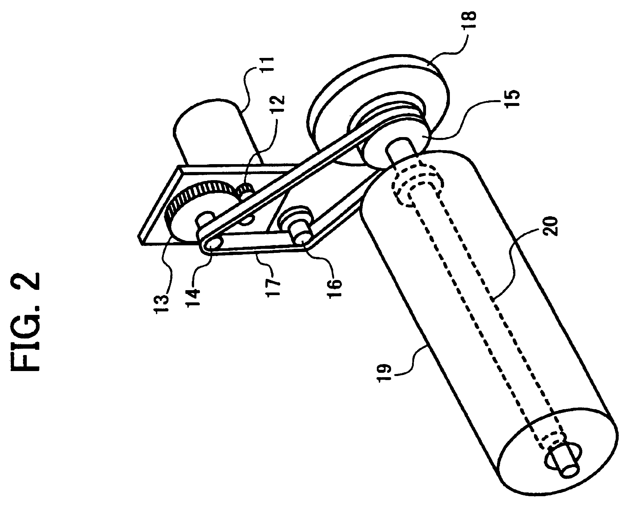
[0041]FIG. 2 is a perspective view of a rotor driver according to the present invention. Rotational torque (drive force) of a pulse motor 11 as a rotation drive source is transmitted to a shaft 20 of a rotor 19 by gears 12 and 13, and a timing belt 17 that form a power transmission system. The timing belt 17 is wound around between a drive pulley 14 and a driven pulley 15, so that it is held under a constant tension by a tension pulley 16. The rotor 19 is fixed to the shaft 20 so that concentricity of the rotor 19 to the driven pulley 15 is maintained through the shaft 20. An encoder 18 as a unit for detecting an angular displacement of the rotor 19 is fixed to the shaft 20 of the rotor 19 through a coupling (not shown). An angular displacement of the shaft 20 detected by the encoder 18 is the same as that of the rotor 19.

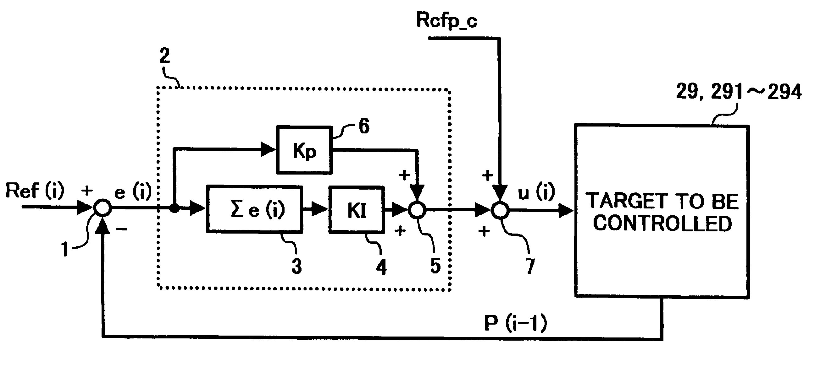
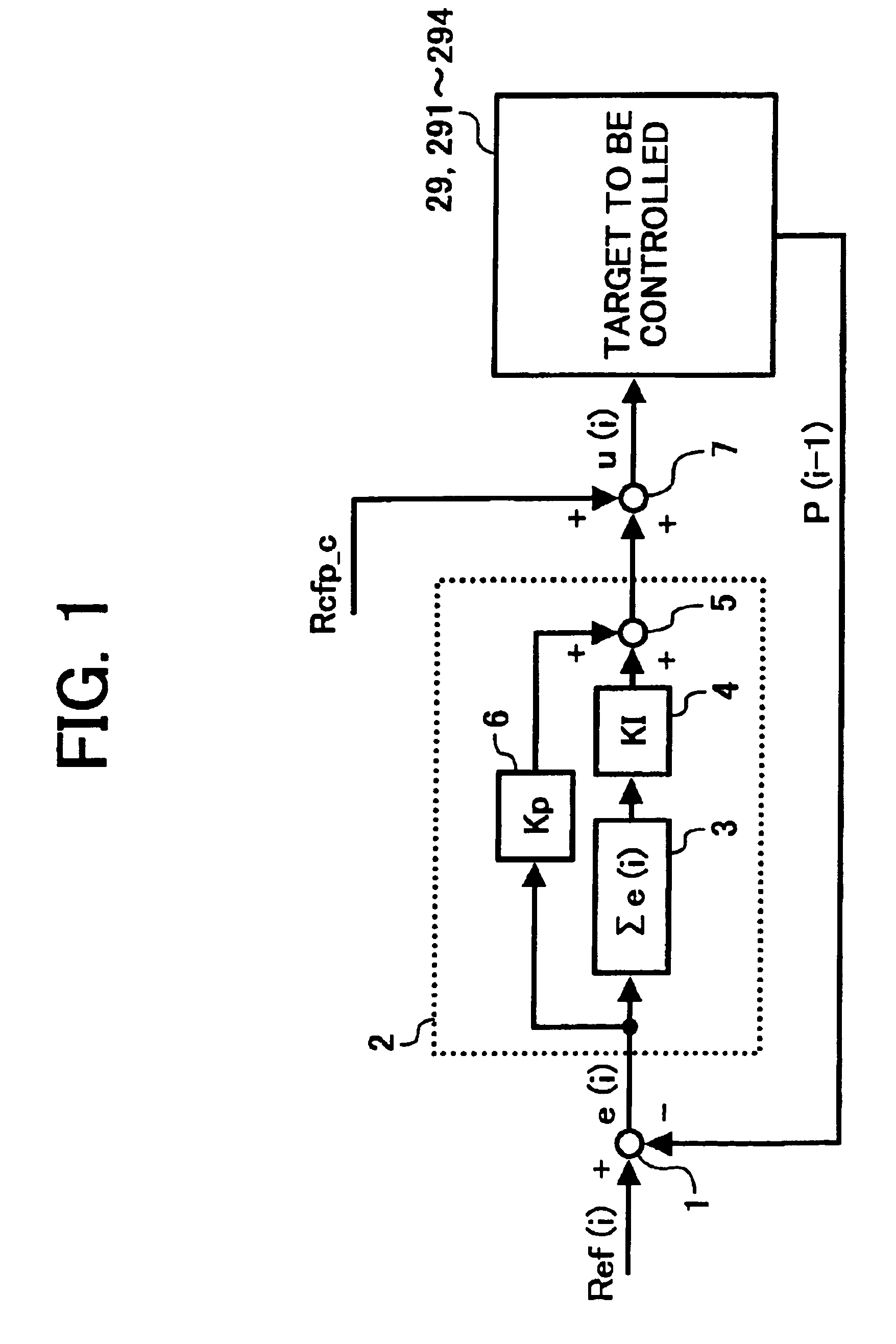
[0042]FIG. 3 is a block diagram of a hardware configuration of a control system of the pulse motor 11 and a target to be controlled according to the first embodime...

second embodiment

[0055]FIG. 5 is a block diagram of a hardware configuration of the control system of the pulse motor 11 and a target to be controlled according to the Reference numeral 292 of FIG. 5 represents the target including the whole rotor drive system, the motor-driving interface 24, the motor driver 25, and a detection interface 262.

[0056]The detection interface 262 processes an output pulse of the encoder 18 to be converted to a digital value. This detection interface 262 includes the counter that counts output pulses of the encoder 18, and multiplies a value counted in the counter by a conversion constant for a preset diagonal displacement of the number of pulses. This detection interface 262 also converts an obtained value to a digital value corresponding to an angular displacement of the drive roller 31. The signal of the digital value corresponding to the angular displacement of the drive roller 31 is transmitted to the microcomputer 21 through the bus 22.

[0057]The motor driver 25 op...

third embodiment

[0064]FIG. 7 is a block diagram of a hardware configuration of the control system of the pulse motor 11 and a target to be controlled according to the Reference numeral 293 of FIG. 7 represents the target including the whole rotor drive system, the motor-driving interface 24, the motor driver 25, and a detection interface 263.

[0065]The detection interface 263 processes an output pulse of the encoder 18 to be converted to a digital value. This detection interface 263 includes the counter that counts output pulses of the encoder 18, and multiplies a value counted in the counter by a conversion constant for a preset diagonal displacement of the number of pulses. The detection interface 263 also converts an obtained value to a digital value corresponding to an angular displacement of the driven roller 32. The signal of the digital value corresponding to the angular displacement of the driven roller 32 is transmitted to the microcomputer 21 through the bus 22.

[0066]The motor driver 25 o...


PUM


Abstract

A drive control method includes detecting an angular displacement of a rotor driven by a pulse motor, calculating a difference between the detected angular displacement and a preset target value of the angular displacement, and calculating a drive pulse frequency of a drive pulse signal used to drive the pulse motor. The pulse motor is driven by the drive pulse signal having the drive pulse frequency to allow the rotor at a constant angular velocity.

Description

CROSS-REFERENCE TO RELATED APPLICATIONS[0001]The present document incorporates by reference the entire contents of Japanese priority documents, 2002-351767 filed in Japan on Dec. 3, 2002 and 2003-307332 filed in Japan on Aug. 29, 2003.BACKGROUND OF THE INVENTION[0002]1) Field of the Invention[0003]The present invention relates to a drive control method and apparatus that controls the drive of a pulse motor so that a rotor driven by the pulse motor rotates at a constant angular velocity or a movable element driven by the pulse motor moves at a constant velocity, and to a belt device, an image forming apparatus, an image reading apparatus, and computer products.[0004]2) Description of the Related Art[0005]A drive control method disclosed in Japanese Patent No. 2754582 is a method of detecting an angular velocity of a transfer roller based on an output pulse signal of an encoder provided on a shaft of the transfer roller as a rotor. In this method, the drive of a pulse motor that rotat...

Claims


Application Information

Patent Timeline
Patent Type & Authority Patents(United States)
IPC IPC(8): H02P5/00H02K41/00G05B19/416
CPCG05B19/416G05B2219/41184
Inventor ANDOH, TOSHIYUKIMATSUDA, HIROMICHIKOMATSU, MAKOTOSHINOHARA, TADASHIMATSUDA, YUUJIKOBAYASHI, KAZUHIKOYOKOKAWA, NOBUTOYOKOYAMA, MASATOMIURA, YOHHEITAKAHASHI, TOSHIYUKIHOSOKAWA, JUN
Owner RICOH KK
Why Eureka
Try Eureka