Driving circuit and method for preventing voltage surges on supply lines while driving a DC motor

Inactive Publication Date: 2005-09-27
POWERWAVE TECH S A R L +1
View PDF8 Cites 19 Cited by
  • Summary
  • Abstract
  • Description
  • Claims
  • Application Information

AI Technical Summary

Benefits of technology

[0018]The circuit has an output coupled to the logic circuits, and an input receiving a signal representative of at least one of the operating parameters belonging to the group of: the voltage on the supply node of the output power stage; the voltage present on at least a winding of the motor; the direction of flow of the current on the supply lines; and the phase difference between the current circulating in at least a winding of the motor and the back

Problems solved by technology

This inversion may cause voltage

Method used


Image

  • Driving circuit and method for preventing voltage surges on supply lines while driving a DC motor
  • Driving circuit and method for preventing voltage surges on supply lines while driving a DC motor
  • Driving circuit and method for preventing voltage surges on supply lines while driving a DC motor

Examples


Example

[0029]To simplify illustration of the features of the invention in the following description, several embodiments of the invention will be treated, and all are related to brushless motors. However, the present invention is not limited to brushless motors, and other kinds of DC motors are readily applicable. In consideration that driving in a switching mode may be used with any kind of DC motor, and it is used in an increasingly large number of applications, the invention will be described for the particular case of driving a motor in a switching mode. However, the invention remains useful and may be implemented in a linear driving system with the necessary changes having been made.

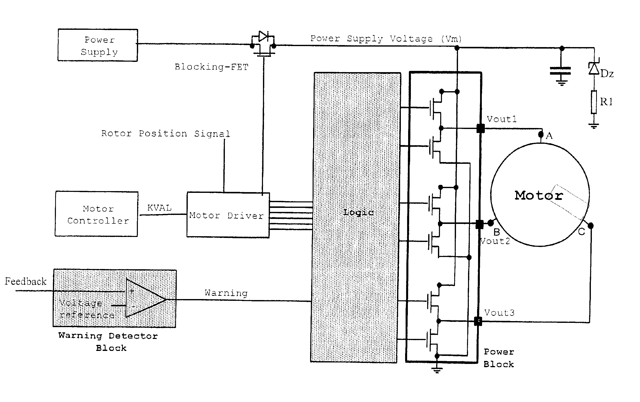
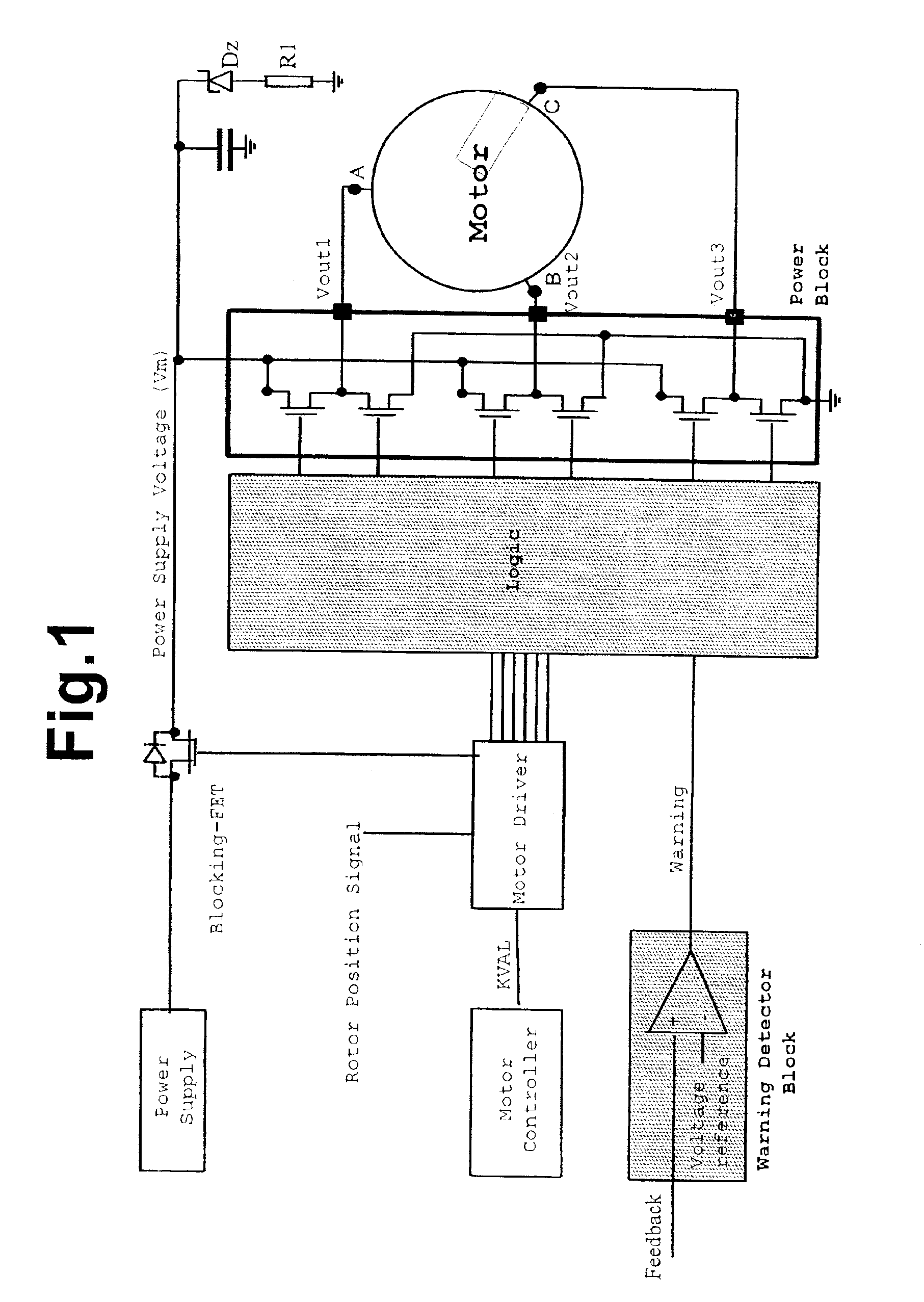
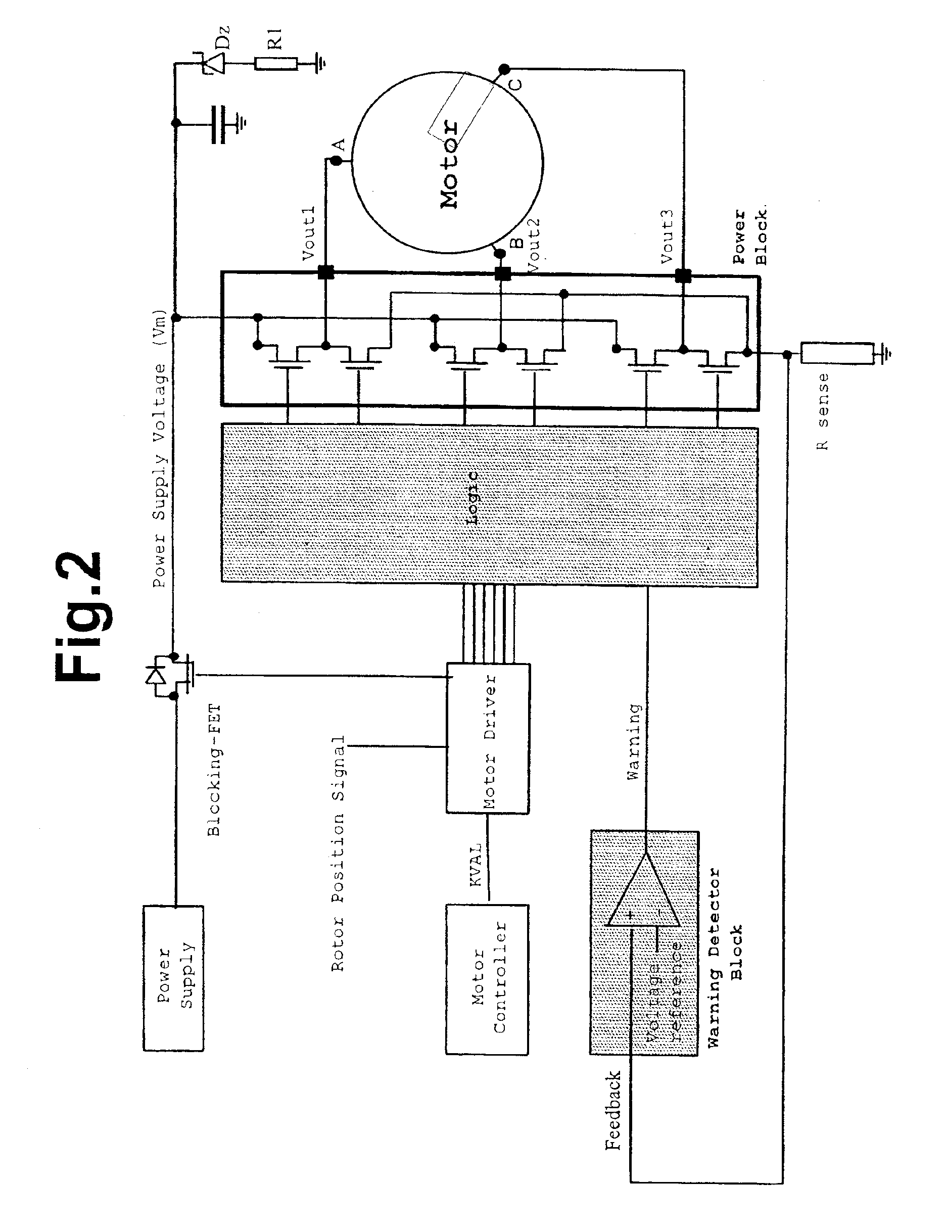
[0030]In the most common case of star or triangle configured motors with three phase windings, the windings may be driven by integrated circuits. The power output stage that drives the phase windings generally comprises a three-phase bridge circuit composed of six BJT or MOS transistors.

[0031]A basic diagr...


PUM


Abstract

A driving circuit of a DC motor includes a control circuit for providing a control signal, and a motor drive circuit commanded by the control circuit for providing respective command signals for the switches of an output power stage connected to the DC motor. The output power stage is connected to a power supply line and drives the windings of the DC motor. The driving circuit prevents generation of voltage surges having a significant magnitude on the power supply line because the driving circuit has logic circuits for preventing any substantial inversion in the direction of current flow in the supply lines when the DC motor operates as a current generator.

Description

FIELD OF THE INVENTION[0001]The present invention relates in general to DC motors, and more particularly, to a driving circuit and a method for preventing voltage surges on the supply lines of a DC motor.BACKGROUND OF THE INVENTION[0002]DC motors are used in a variety of applications. Several methods for varying the speed of the rotor are known, whether the motor has brushes or is a so-called brushless motor.[0003]The speed of brushless motors may be varied by varying the supply voltage of the windings of the stator, for example, by reducing with a rheostat the voltage applied to the terminals of the motor. A motor may also be driven in a switching mode, that is, by coupling the motor terminals alternately to the supply rail and ground potential. This is normally done by using a half bridge stage formed by a pair of switches, commonly MOS transistors of opposite conductivity, driven in phase opposition. The effective voltage applied to the motor terminals is determined by the ratio ...

Claims


Application Information

Patent Timeline
IPC IPC(8): H02P6/00H02P6/24
CPCH02P6/24
Inventor BOSCOLO, MICHELEVITI, MARCOGALBIATI, EZIO
Owner POWERWAVE TECH S A R L
Why Eureka
Try Eureka