Turbine blade clearance on-line measurement system

a technology of blade clearance and measurement system, which is applied in the direction of machines/engines, mechanical equipment, instruments, etc., can solve the problems of reducing the efficiency of the turbine, reducing the accuracy of the clearance, and the damage of seals and/or blade tips, etc., and achieves accurate measurement of the clearance

Inactive Publication Date: 2005-09-27
SIEMENS ENERGY INC
View PDF16 Cites 32 Cited by
  • Summary
  • Abstract
  • Description
  • Claims
  • Application Information

AI Technical Summary

Benefits of technology

[0008]Thus, it is desired to provide a turbine blade clearance monitor and method that can accurately measure the clearance between the blades and blade ring of a turbo-machine. The present invention fulfills this needs by providing an apparatus including an eddy current coil positioned near a location of the stationary portion of a turbo-machine traversed by a rotating blade during operation of the turbo-machine. The apparatus also provides an eddy current tester connected to the edd

Problems solved by technology

The clearance between the stationary seals of a combustion turbine or compressor turbine and the tips of the rotating blades therein must not be so great as to permit an excessive amount of fluid to pass there between, and thereby reducing the efficiency of the turbine.
On the other hand, clearances cannot be too small because high centripetal loading and high temperatures may cause blades to lift or to grow radially.
Such blade lifting or radial growth can cause blade tips to rub the stationary seal and may eventually cause seal and/or blade tip damage.
In addition, the differences in thermal response time of the various turbine components can result in the mechanical interference between stationary and moving parts under certain conditions.
This is certainly the case during the restart of a hot turbine where contact between the compressor/turbine blades and the stationary blade ring has resulted in massive compressor and turbine damage.
Even a slight rub will destroy blade seals and reduce the efficiency of a combustion turbine.
The

Method used


Image

  • Turbine blade clearance on-line measurement system
  • Turbine blade clearance on-line measurement system
  • Turbine blade clearance on-line measurement system

Examples


Embodiment Construction

[0018]Throughout this specification, the term “turbo-machine” is used to refer to a device that includes rotating airfoils contained within a stationary casing used for the purpose of imparting energy into or extracting energy from a fluid passing over the airfoils.

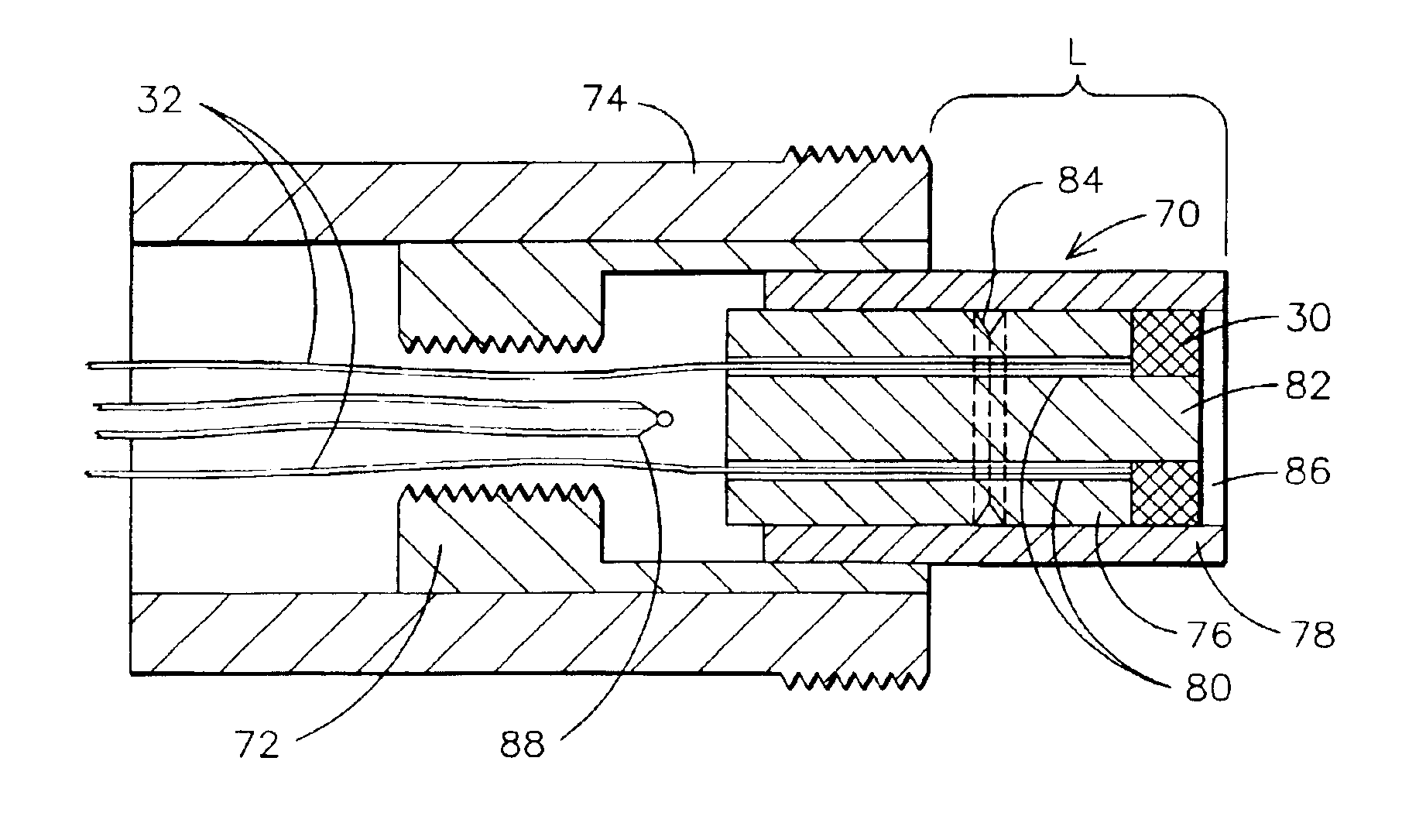
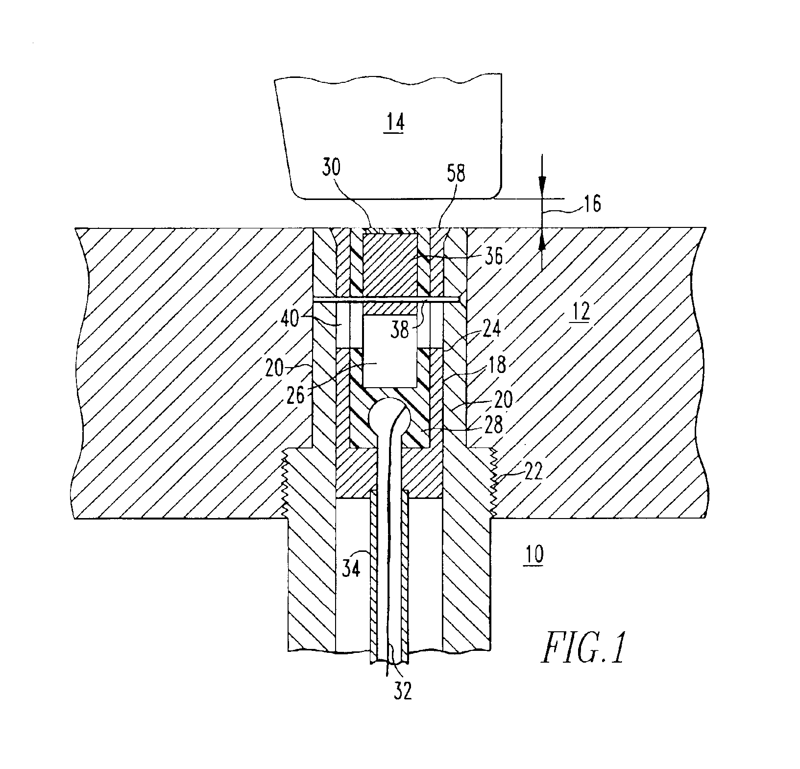
[0019]FIG. 1 illustrates the forward sensing portion of a blade clearance monitoring system 10 for monitoring the clearance 16 between a turbine blade, such as a compressor blade 14 and a stationary component of the turbine such as a blade ring 12. A very small eddy current search coil 30 is employed to provide a short range and sensitive indication by means of a discrete voltage signal level output, of the proximity of the blade tip and search coil in the order of 0.010 inch (0.254 mm). A search coil 30 that can be employed for this purpose preferably has an inner diameter from between 0.020 to 0.050 inch (0.508-1.27 mm). The search coil is mounted at an end of a short throw insertion probe 18. A short throw of approxima...


PUM


Abstract

A system (90) for measuring the gap (16) between a rotating blade (14) and a stationary component (12) of a turbo-machine, including an eddy current coil (30) and an eddy current tester (91). The eddy current tester may excite the coil in a pulsed eddy current testing mode. The coil is positioned in a stationary portion (12) of a turbo-machine traversed by a rotating blade and the eddy current tester is coupled to the eddy current coil to provide an indication responsive to a distance between the blade and the stationary portion as the blade traverses the position. The coil may be mounted in a frangible ceramic pill (70) movably disposed in a housing (74). The coil is positioned near the turbine blade, the coil is excited with a voltage step function (120), and the response (122) of the coil to the step function is detected and processed to determine the proximity of the blade.

Description

[0001]This application is a continuation-in-part of U.S. patent application Ser. No. 10 / 158,954, now U.S. Pat. No. 6,661,222, issued on Dec. 9, 2003, and it claims benefit of the May 31, 2002 filing date thereof.FIELD OF THE INVENTION[0002]The present invention is directed generally to systems for monitoring the clearance between fixed and rotating parts within a turbo-machine.BACKGROUND OF THE INVENTION[0003]The clearance between the stationary seals of a combustion turbine or compressor turbine and the tips of the rotating blades therein must not be so great as to permit an excessive amount of fluid to pass there between, and thereby reducing the efficiency of the turbine. On the other hand, clearances cannot be too small because high centripetal loading and high temperatures may cause blades to lift or to grow radially. Such blade lifting or radial growth can cause blade tips to rub the stationary seal and may eventually cause seal and / or blade tip damage.[0004]In addition, the d...

Claims


Application Information

Patent Timeline
IPC IPC(8): G01B7/14F01D21/00H01F5/00
CPCF01D21/003G01B7/14F05D2270/305
Inventor TWERDOCHLIB, MICHAELBATEMAN, DAVID
Owner SIEMENS ENERGY INC
Why Eureka
Try Eureka