
Television tuner which has leveled a gain deviation in the same band

a technology of gain deviation and television tuner, which is applied in the direction of continuous tuning, discontnuous tuning with seperate pre-tuned circuits, television systems, etc., can solve the problem of expensive cost of varactor

Inactive Publication Date: 2005-09-27
ALPS ALPINE CO LTD
View PDF12 Cites 16 Cited by
  • Summary
  • Abstract
  • Description
  • Claims
  • Application Information

AI Technical Summary

Benefits of technology

[0040]The invention further provides a television tuner characterized in that the double tuning circuit comp

Problems solved by technology

Such a varactor, however, is costly.

Method used


Image

  • Television tuner which has leveled a gain deviation in the same band
  • Television tuner which has leveled a gain deviation in the same band
  • Television tuner which has leveled a gain deviation in the same band

Examples


first embodiment

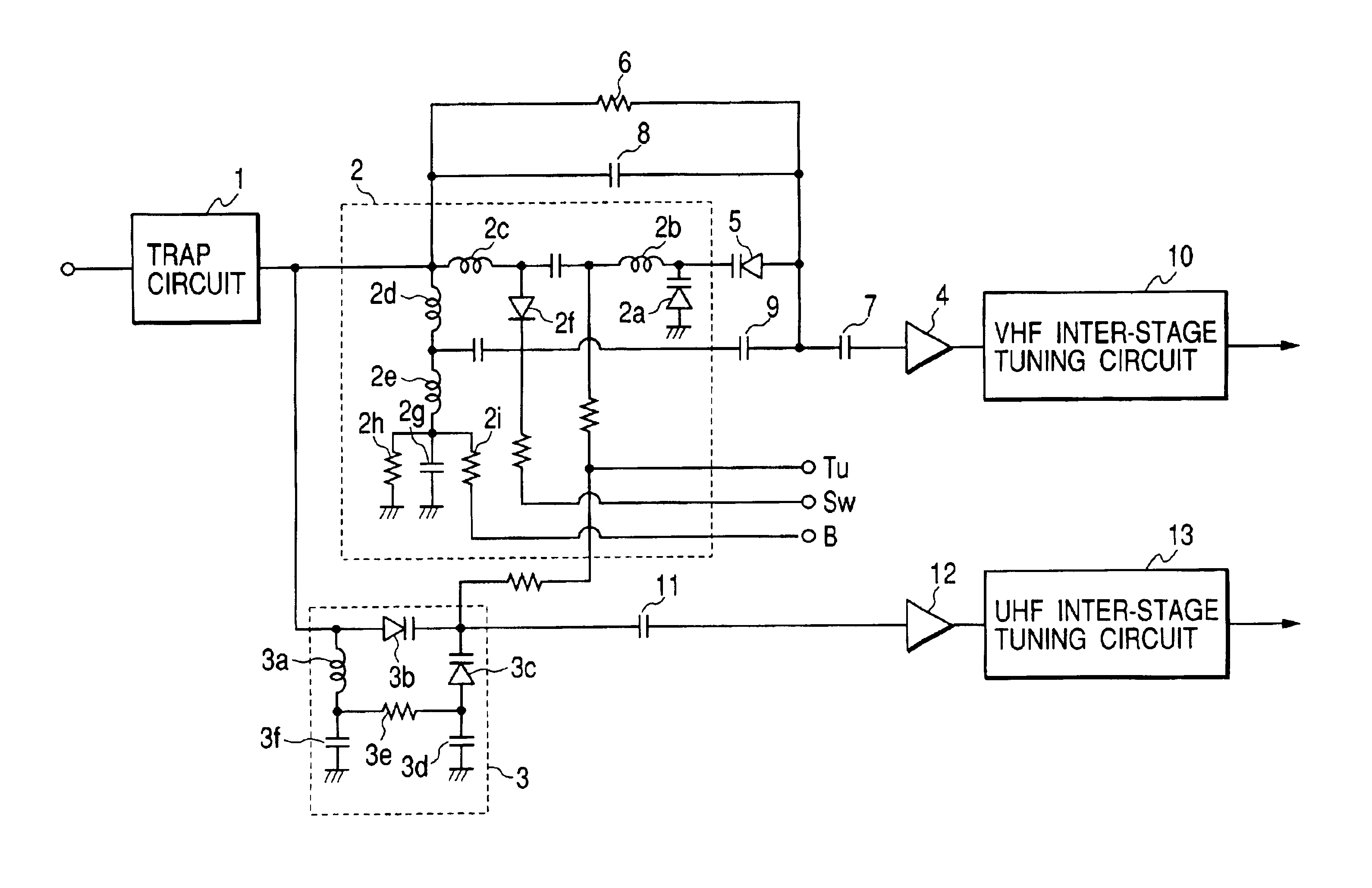
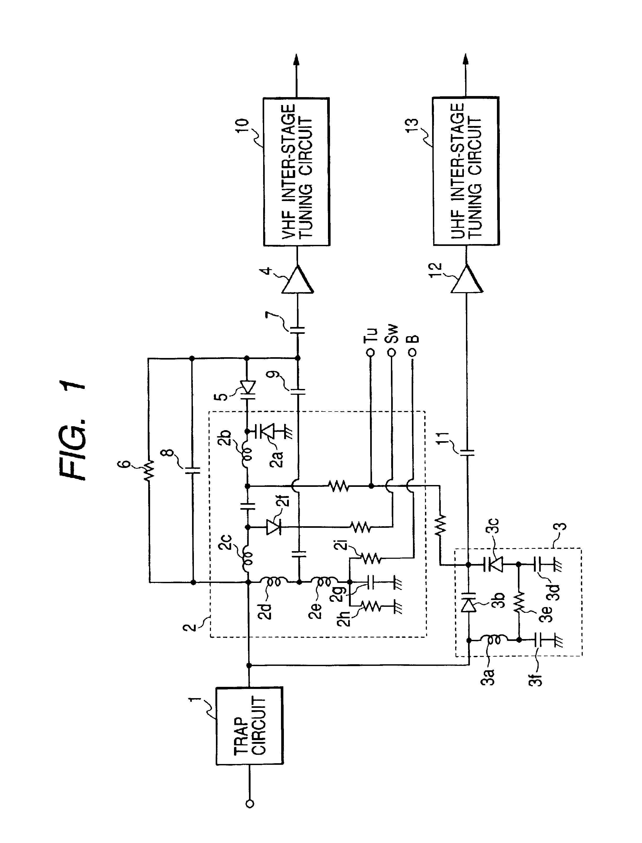
[0054]the invention will be described in accordance with the drawings. In FIG. 1, a television signal in the VHF band to the UHF band is input to a VHF input tuning circuit 2 and a UHF input tuning circuit 3 via a trap circuit 1 for removing unnecessary signals such as an FM broadcast signal.

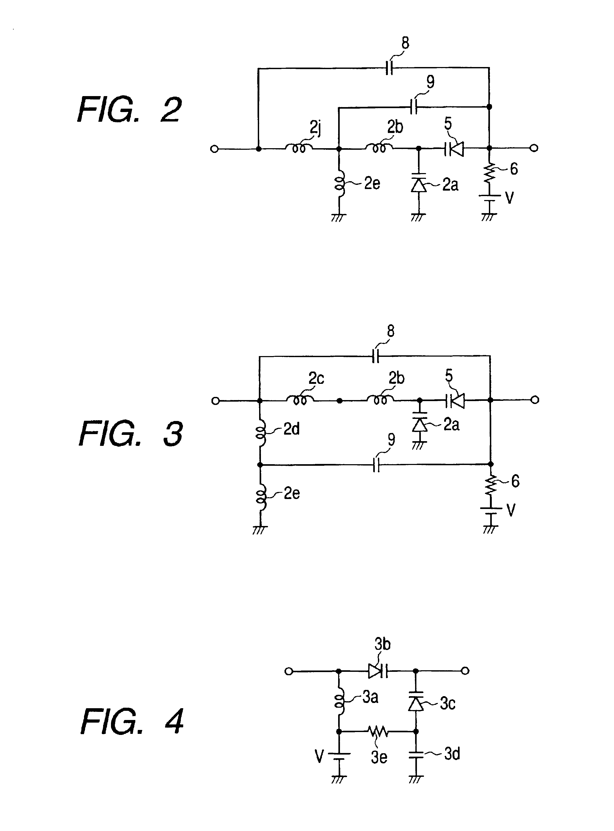
[0055]The VHF input tuning circuit 2 has a tuning varactor diode 2a whose anode is grounded, a high-band coil 2b, a low-band coil 2c, a low-band coil 2d and a high-band coil 2e sequentially connected serially with the cathode of the tuning varactor diode 2a via high frequencies and connected in parallel with the tuning varactor diode 2a via high frequencies, and a switch diode 2f connected in parallel across two low-band coils 2c and 2d via high frequencies. Inductance of the high-band coils 2b, 2e is smaller than that of the low-band coils 2c and 2d. The high-band coil 2e on the low potential side is grounded via high frequencies by a DC cut capacitor 2g. To the connection point of the two low-...

second embodiment

[0072]FIG. 5 shows the invention. In FIG. 5, an input tuning circuit 51 to which a television signal in the VHF band is input comprises a single tuning circuit, in which a switch diode 51a and a varactor diode 51b are provided. The switch diode 51a is switched on / off and accordingly the input tuning circuit 51 is switched so as to be tuned to the high band or low band of the VHF band. The anode of the varactor diode 51b is grounded. A tuning voltage is applied to the cathode of the varactor diode 51b by the tuning voltage terminal Tu. By varying the tuning voltage, the tuning frequency varies in each band.

[0073]A television signal selected by the input tuning circuit 51 is input to the high-frequency amplifier 52 provided in the subsequent stage and amplified therein. An FET (not shown) is used as an amplifying element used in the high-frequency amplifier 52.

[0074]In a stage subsequent to the high-frequency amplifier 52 is provided a double tuning circuit 53. On the preliminary side...


PUM


Abstract

A gain deviation is leveled in the same band by using a varactor diode having the same characteristics as that used in an input tuning circuit for coupling the input tuning circuit and a high frequency amplifier The input tuning circuit has a tuning varactor diode whose tuning frequency varies with a tuning voltage applied to the cathode of the tuning varactor diode, a high-frequency amplifier is provided in a stage subsequent to the input tuning circuit, and a coupling varactor diode for coupling the input tuning circuit to the high-frequency amplifier, in which the cathode of the coupling varactor diode and that of the tuning varactor diode are connected with each other and a bias voltage higher than the voltage at the anode of the tuning varactor diode and lower than the lowest voltage of the tuning voltage is applied to the anode of the coupling varactor diode.

Description

BACKGROUND OF THE INVENTION[0001]1. Field of the Invention[0002]The present invention relates to a television tuner and in particular to a television tuner equipped with a coupling varactor diode.[0003]2. Description of the Related Art[0004]FIG. 8 shows a circuit diagram of a related art television tuner. A television signal in the VHF band to UHF band is input to a VHF input tuning circuit 22 and a UHF input tuning circuit 23 via a trap circuit 21 for removing unnecessary signals such as an FM broadcast signal.[0005]The VHF input tuning circuit 22 has a tuning varactor diode 22a whose anode is grounded, four coils sequentially connected serially with the cathode thereof via high frequencies and connected in parallel with the tuning varactor diode 22a via high frequencies, that is, a high-band coil 22b, a low-band coil 22c, a low-band coil 22d and a high-band coil 22e, and a switch diode 22f connected in parallel across two low-band coils 22c and 22d via high frequencies. Inductance...

Claims


Application Information

Patent Timeline
IPC IPC(8): H03J5/24H03J5/00H03J3/00H03J3/18
CPCH03J3/185H03J5/244
Inventor YAMAMOTO, MASAKI
Owner ALPS ALPINE CO LTD
Learn More