
Process for generating an optical radiation, corresponding source and Raman amplifier including such a source

a technology of optical radiation and corresponding source, applied in the direction of laser details, active medium shape and construction, electrical apparatus, etc., can solve the problem of low output power, and achieve the effect of low noise, high amplification gain, and broadband operation

Inactive Publication Date: 2005-09-27
IPG FIBERTECH
View PDF3 Cites 0 Cited by
  • Summary
  • Abstract
  • Description
  • Claims
  • Application Information

AI Technical Summary

Benefits of technology

[0013]The present invention provides a solution for making a broadband, low noise and high power laser source for use as a pumping source for a Raman fiber amplifier, presenting broadband operation and high amplification gain. The invention may be practiced in both distributed and discrete configurations, both of which are more thoroughly described below.

Problems solved by technology

The main drawbacks of these solutions are essentially related to system reliability (penalised by the need of using a high number of sources and respective coupling components) and to the fact that output power is however rather low, also due to intrinsic losses related to multiplexing operations of the radiation generated by the single sources.

Method used


Image

  • Process for generating an optical radiation, corresponding source and Raman amplifier including such a source
  • Process for generating an optical radiation, corresponding source and Raman amplifier including such a source

Examples


Embodiment Construction

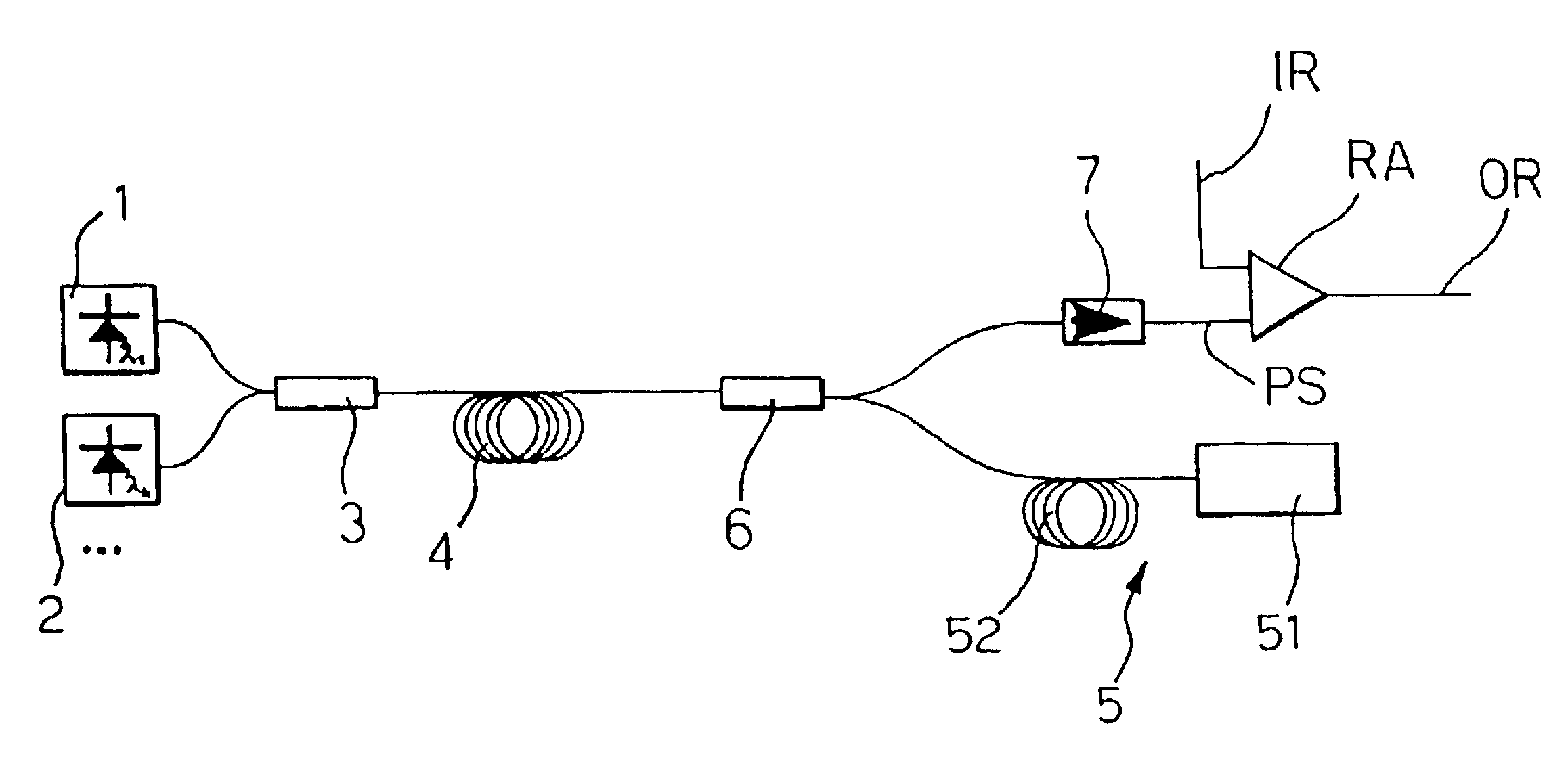
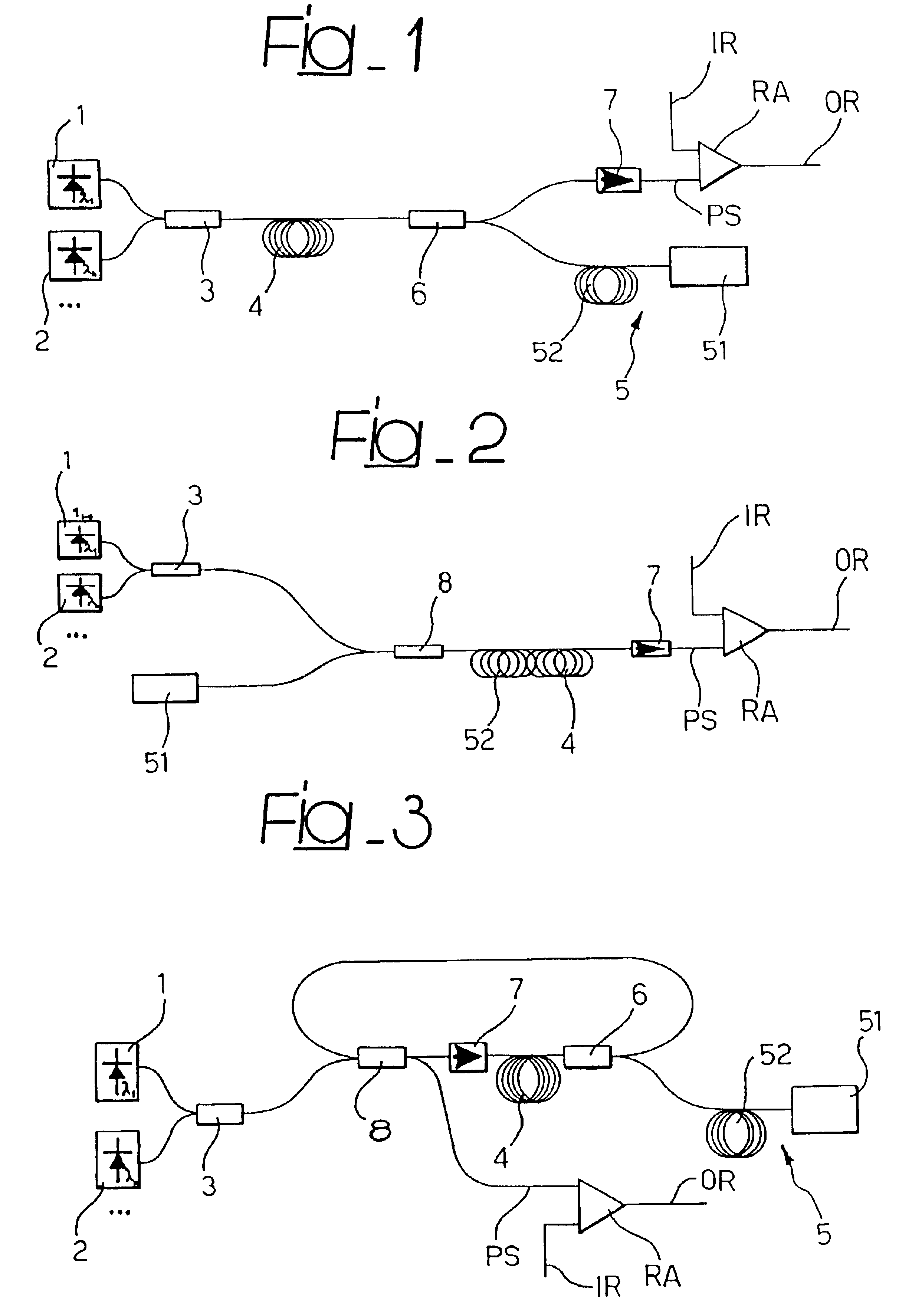
[0019]This invention will now be described, by way of example only, by referring to the accompanying drawings, comprising three figures, indicated as FIG. 1, FIG. 2 and FIG. 3, respectively. The figures illustrate three different possible embodiments of a broadband, low noise and high-power laser radiation source, made according to this invention.

[0020]In all three possible embodiments illustrated in the accompanying drawings (which do not comprehensively include all the various possible embodiments of this invention), reference PS indicates a broadband, high power laser signal. Specifically, the PS signal can be used as a pumping signal in a Raman effect amplifier RA inserted in a fiber optic signal transmission system to generate an amplified output signal OR from an input signal IR.

[0021]To help comprehension, without limiting the scope of this invention, the pumping signal PS can be a signal with a bandwidth of several tens of nanometers (e.g. in the range from 1420 to 1500 nano...


PUM


Abstract

An optical radiation adapted for use in Raman amplification in a given band, is generated from a low power optical radiation with a respective bandwidth, generated by a plurality of master oscillators, such as low-power laser diodes whose output radiation is multiplexed by a multiplexer. A Raman amplification medium is provided, such as a length of optical fiber, and an additional optical radiation adapted for use in Raman amplification in said Raman amplification medium is generated. Both the low-power optical radiation and the additional optical radiation are injected into the medium so to produce, by the Raman effect induced in the medium, the output optical radiation.

Description

CROSS REFERENCE TO RELATED APPLICATIONS[0001]In accordance with 35 U.S.C. § 119, this application claims priority to EPO Application Number 01830618.3, filed on Sep. 28, 2001, entitled “A PROCESS FOR GENERATING AN OPTICAL RADIATION, CORRESPONDING SOURCE AND RAMAN AMPLIFIER INCLUDING SUCH A SOURCE,” which is hereby incorporated by reference in its entirety as if fully disclosed herein.BACKGROUND OF THE INVENTION[0002]1. Field of the Invention[0003]This invention relates to amplification techniques based on the Raman effect and was developed with particular reference to the need of developing broadband and high-power laser sources which can be used in Raman amplifiers for amplifying optical signals on fibers.[0004]2. Description of Background Art[0005]In fiber optic transmission systems, the continuous growth in transmission bandwidth requirements has pushed research activities in two main directions: increasing the signal frequency (bit rate) and increasing the number of channels ada...

Claims


Application Information

Patent Timeline
Patent Type & Authority Patents(United States)
IPC IPC(8): H01S3/30H01S3/16H01S3/094H01S3/06H01S3/067
CPCH01S3/302H01S3/06754H01S3/094046H01S3/094096H01S3/1618
Inventor CATTANEO, STEFANOCECCHI, STEFANO
Owner IPG FIBERTECH
Learn More