Phase splitter using digital delay locked loops

a phase splitter and digital delay technology, applied in the field of integrated circuits, can solve the problems that resolution may not provide a satisfactory level of accuracy for some devices

Inactive Publication Date: 2005-09-27
ROUND ROCK RES LLC
View PDF9 Cites 61 Cited by
  • Summary
  • Abstract
  • Description
  • Claims
  • Application Information

AI Technical Summary

Problems solved by technology

This resolution may not provide a satisfactory level of accuracy for some devices, especially for high speed devices such as new generations of memory devices.

Method used


Image

  • Phase splitter using digital delay locked loops
  • Phase splitter using digital delay locked loops
  • Phase splitter using digital delay locked loops

Examples


Embodiment Construction

[0019]The following detailed description refers to the accompanying drawings which form a part hereof, and show by way of illustration specific embodiments in which the invention may be practiced. These embodiments are described in sufficient detail to enable those skilled in the art to practice the invention, and it is to be understood that other embodiments may be utilized and that logical, mechanical and electrical changes may be made without departing from the spirit and scope of the present invention. The following detailed description is, therefore, not to be taken in a limiting sense, and the scope of the invention is defined only by the appended claims.

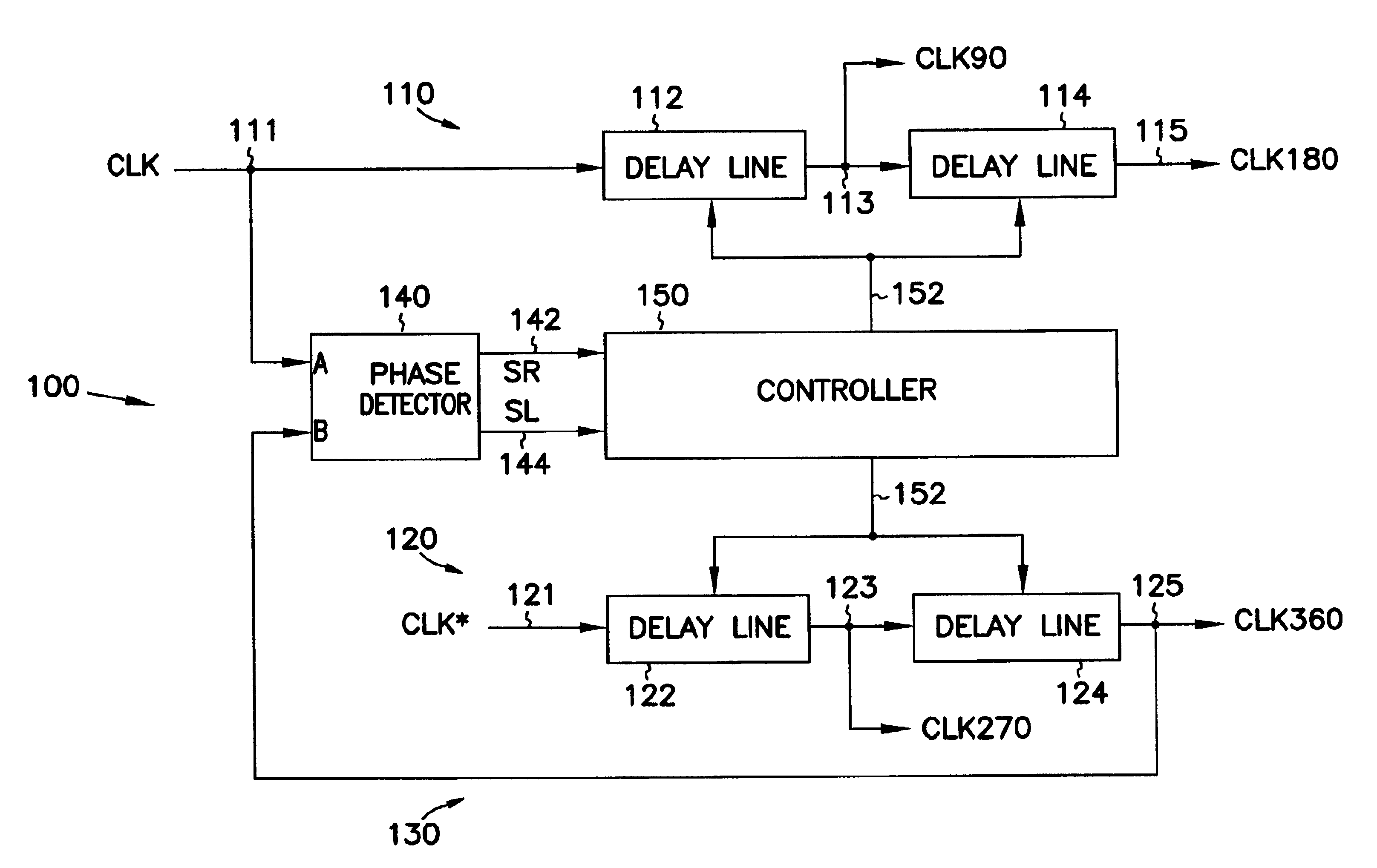
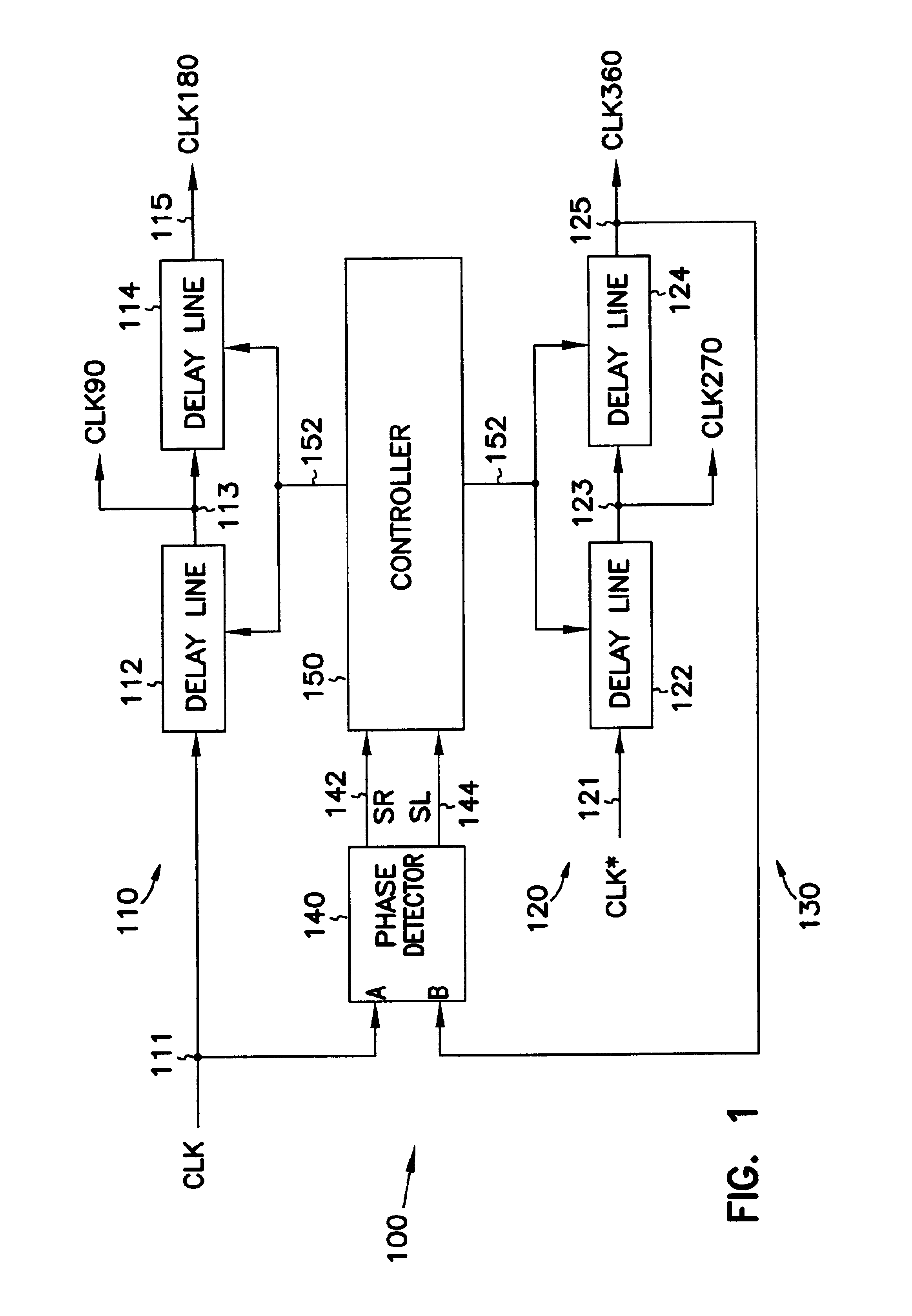
[0020]FIG. 1 is a block diagram of a phase splitter according to one embodiment of the invention. Digital phase splitter 100 includes first and second forward paths 110 and 120, and a feedback path 130. Each of the forward paths 110 and 120 includes two delay lines.

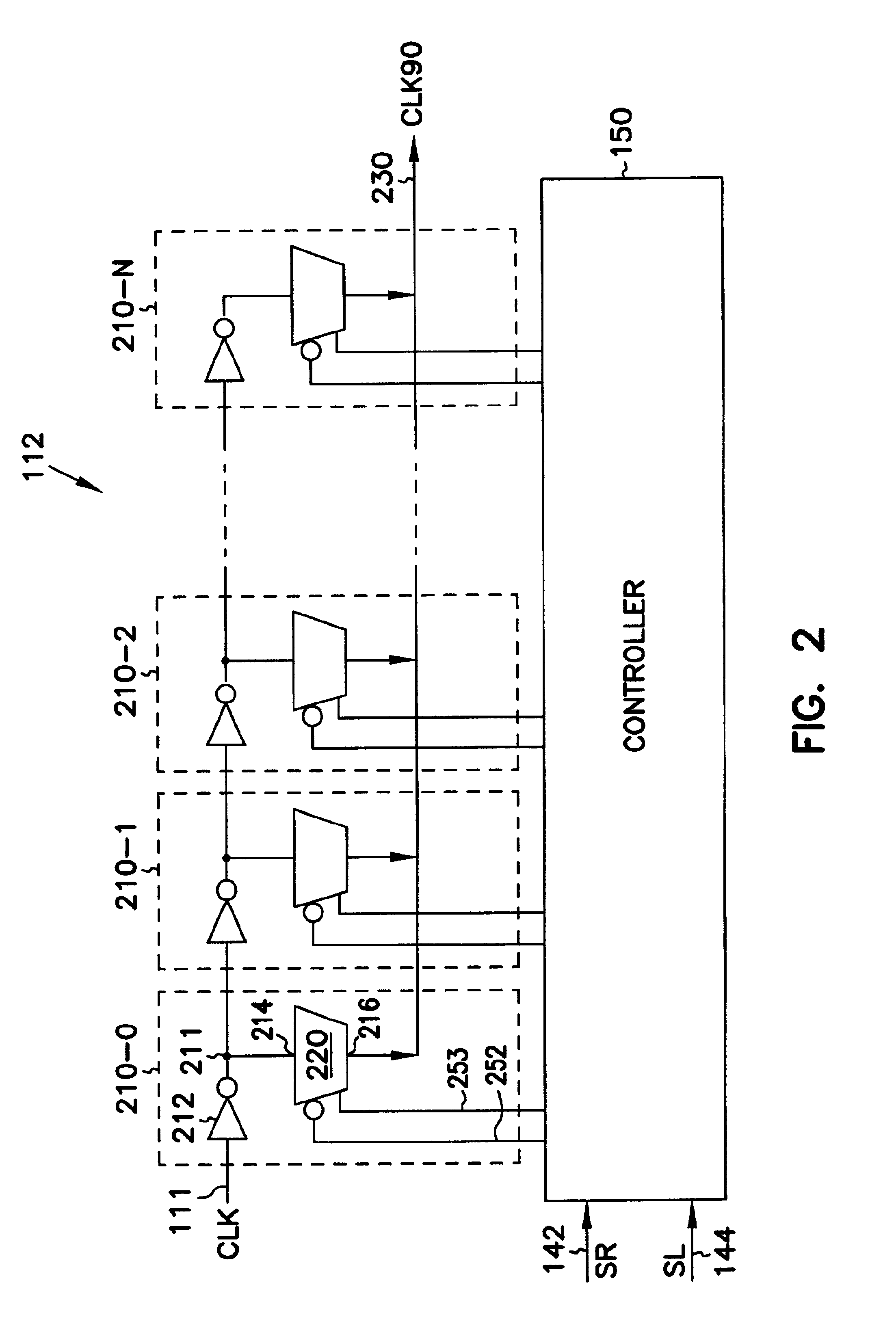
[0021]Forward path 110 includes a delay line 112 connected to ...


PUM


Abstract

A phase splitter using digital delay locked loop (DLL) to receive complementary input clock signals to generate a plurality of output signals having different phase shifts. When the DLL is locked, the delay resolution of the phase splitter is equal to two delay stages of the DLL.

Description

TECHNICAL FIELD OF THE INVENTION[0001]The present invention relates generally to integrated circuits (ICs), and in particular to generating multiple clock signals for an IC.BACKGROUND OF THE INVENTION[0002]In an integrated circuit, a clock signal having a different phase shift with the system clock signal is sometimes required for a specific function. For instance, in one method of capturing a data signal, a clock signal 90 degrees out of phase with the system clock is needed. This clock signal is normally referred to as a quadrature clock signal.[0003]Conventionally, the quadrature clock signal can be generated by a phase splitter using analog or digital delay locked loop (DLL). A traditional phase splitter using digital DLL has four delay segments connected in series. Each of the delay segments has a plurality of delay stages to provide a quarter of clock cycle delay to an input or system clock signal. Together, the four delay lines generate four output clock signals having 90, 18...

Claims


Application Information

Patent Timeline
Patent Type & Authority Patents(United States)
IPC IPC(8): H03L7/087H03L7/08H03L7/089H03K5/15H03L7/081
CPCH03K5/15013H03L7/0805H03L7/0814H03L7/087H03L7/089H03L7/0818H03L7/0816
Inventor LIN, FENGBAKER, R. JACOB
Owner ROUND ROCK RES LLC
Why Eureka
Try Eureka