Apparatus and method for detecting surface defects on a workpiece such as a rolled/drawn metal bar

a technology of surface defects and apparatus, applied in the field of apparatus and methods for detecting surface defects on workpieces, can solve the problems of preventing the use of many inspection technologies, unable to overcome challenges that conventional inspection approaches have not been able to overcome, and providing no reliable means to detect such defects. , to achieve the effect of effective use of image and detection of defects on non-flat surfaces, high speed and increased working distan

Active Publication Date: 2005-09-27
OG TECH INC
View PDF36 Cites 38 Cited by
  • Summary
  • Abstract
  • Description
  • Claims
  • Application Information

AI Technical Summary

Benefits of technology

[0019]One advantage of the present invention is that it may be effectively employed in the production of metal bars with the aforementioned characteristics, namely, those that may be at a manufacturing temperature, perhaps even hot enough to produce self-emitted radiation, as well as those subject to rotation relative to a longitudinal axis and may potentially be traveling at a very high speed. Others advantages of the present invention include (i) effectively employed to image and detect defects on non-flat surfaces; (ii) use for inspecting metal bars regardless of its temperature; (iii) use for inspecting metal bars traveling at speeds at or faster than 100 m / s; (iv) providing an increased working distance to the metal bar surface, thus minimizing or eliminating the problems set forth in the Background for eddy-current based instruments; (v) providing an output comprising quantitative data with verifiable defective site images; (vi) inspection of the workpiece even before the scale forms on its surface; (vii) suitable for use in inspection at any stage (between the reducing stands or at the end of the line) in the reducing process, not affected by or relying upon transient effects; (viii) providing real-time or near real-time surface quality information; (ix) providing a system absent of any moving sensing heads, thus minimizing or eliminating the problems of moving components set forth in the Background; and (x) providing a system needing only very small gap (less than 50 mm) capable of operating between metal bar guiding conduit sections. However, an apparatus and / or method need not have every one of the foregoing advantages, or even a majority of them. The invention being limited only by the appended claims.
[0020]A system is provided for imaging an elongate bar extending along a longitudinal axis. The system includes an image acquisition assembly, a line light assembly, and a computing unit. The image acquisition assembly has a field of view configured to image a first predetermined width over a circumference of a surface of the bar to define an image belt. The image acquisition assembly is further configured to produce image data corresponding to the acquired image belt.
[0021]The line light assembly is configured to project a light line belt having a second predetermined width onto the surface of the bar. The light line assembly is disposed, for example by alignment, relative to the image acquisition assembly such that the image belt is within the light line belt. The light line assembly is further configured such that a light intensity is substantially uniform along the image belt when the light is collected by each of the image acquisition sensors.
[0022]Finally, the computing unit is coupled to the image acquisition assembly and is configured to receive image data for a plurality of image belts acquired by the image acquisition assembly as the bar moves along the longitudinal axis. The computing unit is further configured to process the image data to detect predetermined surface features of the bar. In a preferred embodiment, the detected features are surface defects and the image acquisition assembly includes n digital cameras, where n is an integer 3 or greater, arranged so that a combined field of view of the cameras corresponds to the image belt.
[0023]A method of imaging a metal bar is also presented.

Problems solved by technology

However, the conventional art provides no reliable means to detect such defects.
There are several challenges that conventional inspection approaches have been unable to overcome.
First, in the case where inspection occurs while the metal bar products are “hot,” the temperature can be as high as 1,100° C., preventing the use of many inspection technologies.
Conventional inspection approaches simply cannot accommodate such high traveling speeds.
The space, therefore, for any inspection device is extremely limited.
While it is known to apply various imaging approaches to the inspection of cast or rolled Metal Flats, imaging technologies have heretofore not been used in Long Products (i.e., metal bar) inspection.
Conventional imaging systems are not believed capable for use in inspecting metal bars and the like because the geometry of the metal bars invalidate the illumination and imaging designs that are used to enhance / capture defects on flat surfaces. FIG. 4 illustrates the differences of applying illumination and of capturing images on a flat workpiece versus a round workpiece.
However, this approach has several drawbacks.
Moreover, it is not quantitative in the sense that it is NOT able to describe the nature of the detected defect.
Finally, eddy-current approaches are incapable of detecting certain types of defects.
As a result, the inspection outcome from eddy current devices is not used by the metal industry for a deterministic judgment on the quality of a specific product.
Rather, the output of eddy current-based instruments is only used for qualitative analysis, such as “this batch of steel bars is generally worse than the batch produced last week,” in the Reducing Process for process control purposes, for example, only.
However, many of the restrictions associated with eddy current-based instruments, such as the short working distance, apply with equal force.
The use of these technologies, however, is restricted.
First, these techniques can only be used on “cold” metal bars.
That is, these technologies cannot be used for in-line inspection during or shortly after hot rolling applications.
In addition, the use of magnetic penetrant is messy and cumbersome.
Such rotating mechanism limits the application of this device in metal bar inspection with high traveling speeds, typically used at about 3 m / s.
Such device is also expensive due to the moving sensing head design.
The combination of induction heating and infrared imaging is based on the fact that induction current is only formed on the surface of the metal bar, and the surface defects on the metal bar will result in higher electrical resistance.
There are issues associated with this approach in that (a) such faster heat up is a transient effect and thus timing (time to take images) is very critical; and (b) infrared sensors are not available for very high data rates and therefore cannot support metal bars with high traveling speed.
However, post-manufacturing inspection often is not possible because the product is so long and coiled up, making the bar surfaces not accessible for cold inspection technologies.
Currently, real-time inspection of metal bars manufactured with Reducing Processes is very limited.
Customer complaints may therefore appear 3 to 6 months later due to surface defects on the metal bar products that are not immediately apparent to the customer.
Such complaints cost the metal bar suppliers (i.e., manufacturers).

Method used


Image

  • Apparatus and method for detecting surface defects on a workpiece such as a rolled/drawn metal bar
  • Apparatus and method for detecting surface defects on a workpiece such as a rolled/drawn metal bar
  • Apparatus and method for detecting surface defects on a workpiece such as a rolled/drawn metal bar

Examples


Embodiment Construction

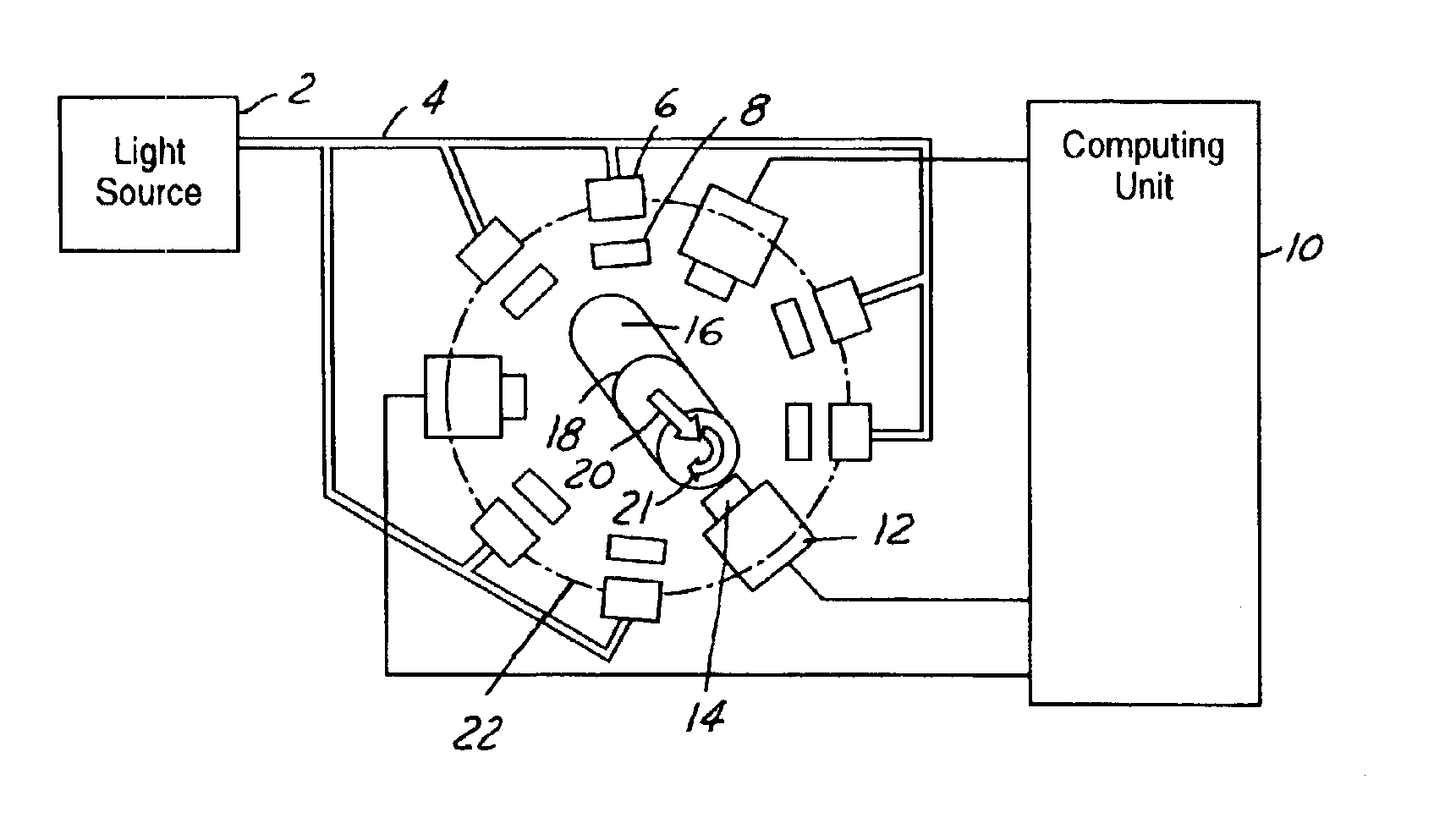
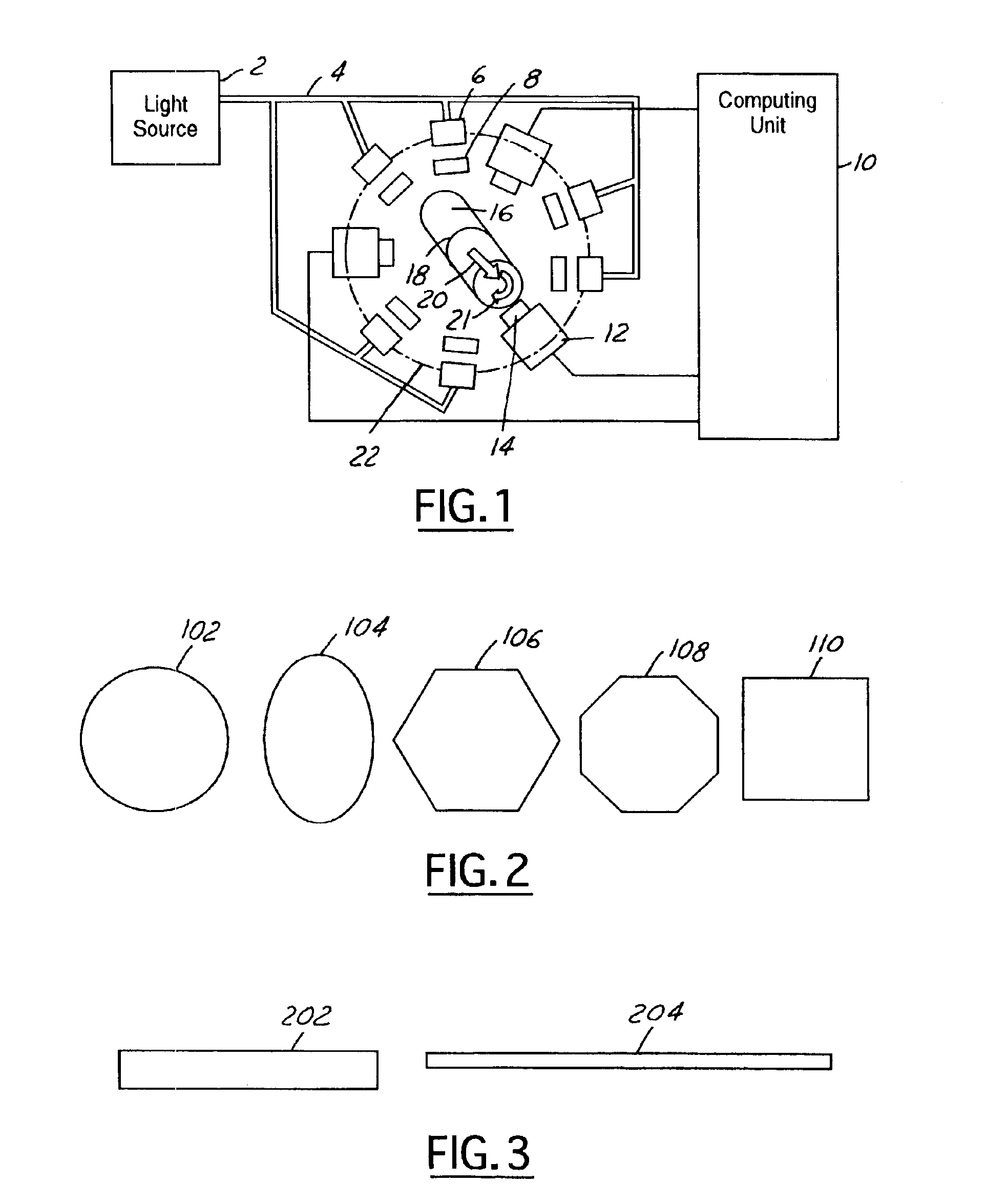
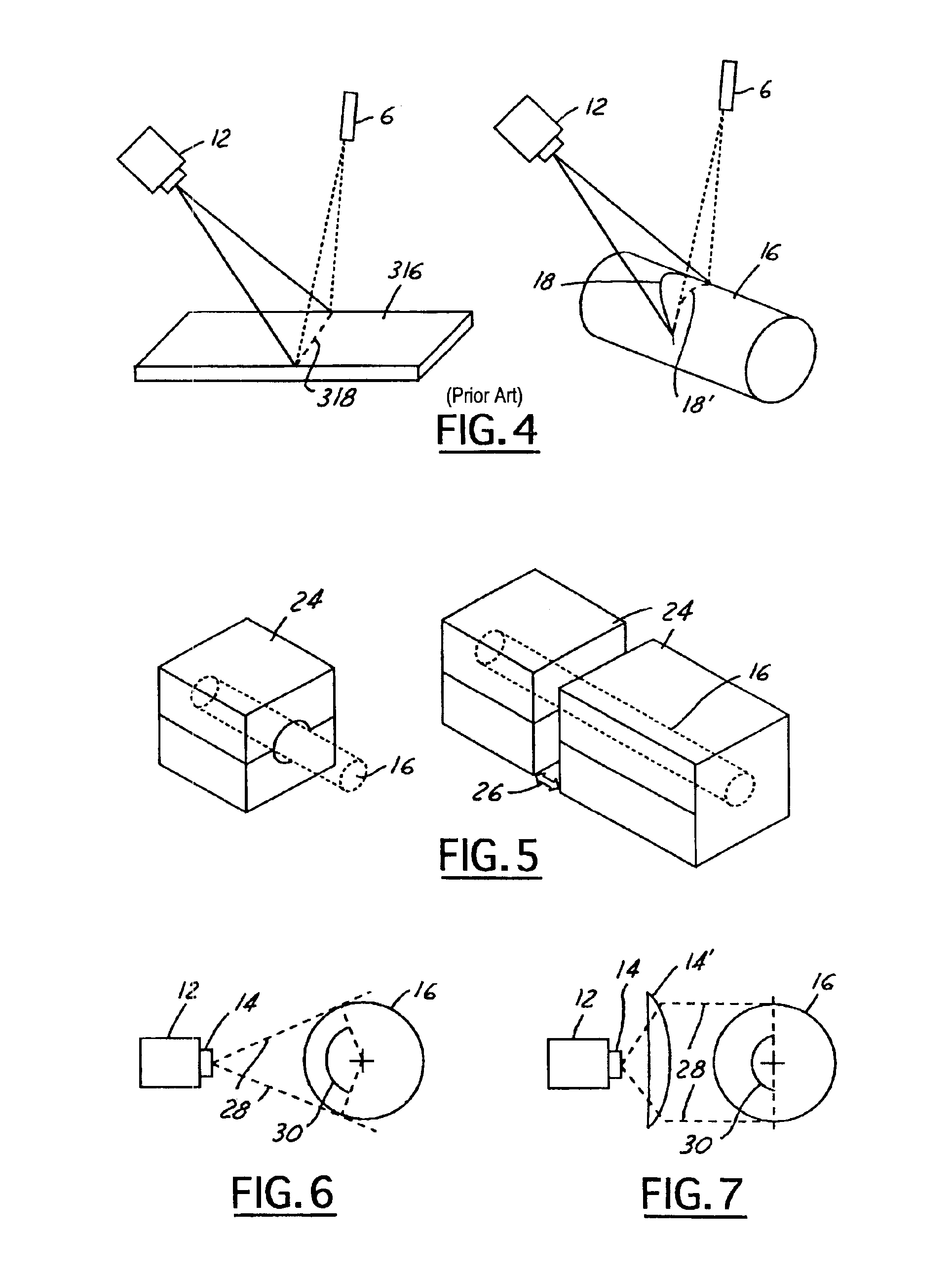
[0041]The present invention permits automated inspection of metal bars for surface defects as the metal bars are being rolled, drawn or the like (i.e., the reducing process described in the Background of the Invention). FIG. 1 schematically illustrates a preferred embodiment in accordance with the present invention.

[0042]Before proceeding to a detailed description of the present invention keyed to the drawings, a general overview will be set forth. The present invention provides the following features:[0043]1. Capable of working for metal bars manufactured through reducing processes at different cross section geometry;[0044]2. Capable of working for metal bars in-line at a bar temperature up to 1,650° C.;[0045]3. Capable of working for metal bars traveling at 100 m / s or higher;[0046]4. Capable of detecting surface defects whose critical dimensions are as small as 0.025 mm;[0047]5. Capable of reporting the defect nature such as its size, location (on the bar), image, and the like;[00...


PUM

PropertyMeasurementUnit
anglesaaaaaaaaaa
temperatureaaaaaaaaaa
speedaaaaaaaaaa

Abstract

The present invention is directed to solving the problems associated with the detection of surface defects on metal bars as well as the problems associated with applying metal flat inspection systems to metal bars for non-destructive surface defects detection. A specially designed imaging system, which is comprised of a computing unit, line lights and high data rate line scan cameras, is developed for the aforementioned purpose. The target application is the metal bars (1) that have a circumference / cross-section-area ratio equal to or smaller than 4.25 when the cross section area is unity for the given shape, (2) whose cross-sections are round, oval, or in the shape of a polygon, and (3) are manufactured by mechanically cross-section reduction processes. The said metal can be steel, stainless steel, aluminum, copper, bronze, titanium, nickel, and so forth, and / or their alloys. The said metal bars can be at the temperature when they are being manufactured.

Description

CROSS-REFERENCE TO RELATED APPLICATIONS[0001]This application claims the benefit of U.S. Provisional Application Ser. No. 60 / 430,549 filed Dec. 3, 2002, the disclosure of which is hereby incorporated by reference in its entirety.STATEMENT REGARDING FEDERALLY FUNDED RESEARCH[0002]This invention was made with United States government support under Cooperative Agreement No. 70NANBOH3014 awarded by the National Institute of Standards and Technology (NIST). The United States government has certain rights in the invention.BACKGROUND OF THE INVENTION[0003]1. Related Field[0004]The present invention relates generally to an imaging system that can image the surface details of a workpiece, such as a rolled / drawn metal bar.[0005]2. Description of the Related Art[0006]It is known to produce a metal bar by a mechanical process such as rolling or drawing. Such metal bar is different than a metal slab, bloom, or strip (hereafter referenced as Metal Flat) in that the cross section of such a bar has...

Claims


Application Information

Patent Timeline
Patent Type & Authority Patents(United States)
IPC IPC(8): G01B11/30G01N21/88G01N21/95G01N21/952G06K9/00H04N9/44H04N9/47H04N7/18G01B
CPCG01N21/952H04N7/18G01N2201/084G01N2201/0826
Inventor CHANG, TZYY-SHUHGUTCHESS, DANIELHUANG, HSUN-HAU
Owner OG TECH INC
Why Eureka
Try Eureka