Method of processing seismic data

Inactive Publication Date: 2005-09-27
GECO PRAKLA UK
View PDF3 Cites 11 Cited by
  • Summary
  • Abstract
  • Description
  • Claims
  • Application Information

AI Technical Summary

Benefits of technology

[0011]It has been appreciated that applying the shortest ray-path length criterion will virtually never result in a low amplitude signal. While the physical length of the ray will vary in response to changes in the velocity model, the physical ray length is less susceptible to such changes than is the estimate of the amplitude. The reason for this is that amplitude is related to the curvature of the rays. Thus small errors in the ray paths can produce large errors in

Problems solved by technology

Thus small errors in the ray paths can

Method used


Image

  • Method of processing seismic data
  • Method of processing seismic data
  • Method of processing seismic data

Examples


Embodiment Construction

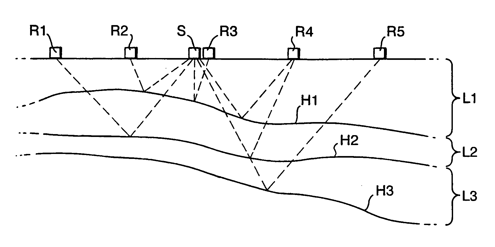
[0019]In FIG. 1, a seismic source S, for example an explosive, is located on the surface of the earth together with a plurality of geophones R1 to R5. Typically, there will be hundreds of geophones arranged in a two dimensional or a three dimensional array over the surface of the earth. For simplicity, only five geophones R1 to R5 are shown. Seismic signal paths (“ray paths”) are shown in broken lines between the source S and the geophones R1 to R5 via subsurface layers L1, L2, and L3. The ray paths are shown reflecting from a number of horizons H1, H2, and H3. Only some of the ray paths are shown for clarity.

[0020]Because the seismic signals will travel at different speeds in the layers (typically the speed of propagation will increase with an increase in depth) it is not straightforward to locate the horizons H1, H2, and H3. The data from each horizon is generally separated and a seismic energy propagation model (i.e. an estimate of the subsurface acoustic velocities) of the subsu...


PUM


Abstract

A method of processing seismic data using a seismic energy propagation model of the subsurface is disclosed. The method assigns seismic source, seismic receiver, and reflection point locations to the propagation model; identifies a plurality of alternative raypaths consistent with the propagation model that originate at said seismic source location, reflect at said reflection point location, and terminate at said seismic receiver location; selects a raypath from the plurality of alternative raypaths having a shortest ray length, and utilizes the selected raypath in subsequent seismic processing.

Description

BACKGROUND OF THE INVENTION[0001]1. Field of the Invention[0002]The present invention relates to a method of processing seismic data.[0003]2. Description of Related Art[0004]Seismic data is collected in order to analyse the sub-surface of the earth, in particular for hydrocarbon exploration. Seismic data for analysing sub-surface structures may be collected on land or, over water, using sea-going vessels. In order to obtain the data, a seismic source which may comprise explosives (on land) or an impulse of compressed air or airguns (at sea) is provided. The seismic data signals reflected by the various layers beneath the surface of the earth are known as traces and are sensed by a large number, typically hundreds, of sensors such as geophones on land and hydrophones at sea. The reflected signals are recorded and the results are analysed to derive an indication of the layer formations beneath the sub-surface. Such indications may then be used to assess the likelihood of hydrocarbon d...

Claims


Application Information

Patent Timeline
IPC IPC(8): G01V1/28
CPCG01V1/282G01V2210/671
Inventor NICHOLS, DAVID EDWARD
Owner GECO PRAKLA UK
Why Eureka
Try Eureka