
Variable rate and clarity ice making apparatus

a variable rate and clarity technology, applied in the field of automatic icemaking machines, can solve the problems of cloudy ice, inability to remove significant amounts of dissolved gas, and inability to control the freeze front direction well

Inactive Publication Date: 2005-10-04
ADAMSKI JOSEPH R
View PDF2 Cites 118 Cited by
  • Summary
  • Abstract
  • Description
  • Claims
  • Application Information

AI Technical Summary

Benefits of technology

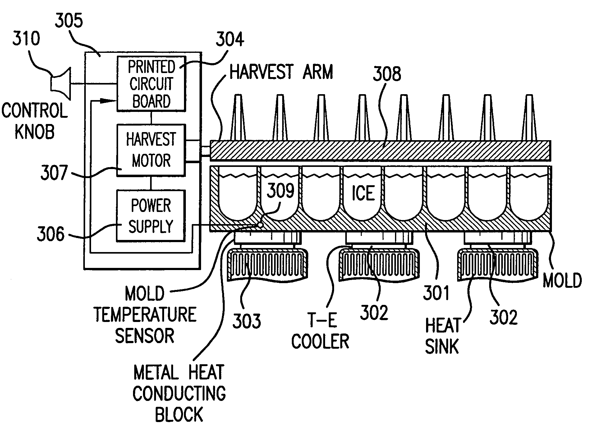
[0014]One important feature of the invention is that the sensible heat removal portions of ice cube making at the beginning and end of the process are accelerated with no impact on clarity of the cube, and the latent heat removal portion of the ice making process is accurately controlled to grow the clearest ice possible.

Problems solved by technology

This sequence of freeze-harvest-refill events results in the most “pounds per hour” of ice possible; however, rapid freezing directly contributes to the creation of cloudy ice.
This is because the typical water freezing rate exceeds the diffusion rate of the impurities in the water (typically dissolved gases such as nitrogen or carbon dioxide) and the freeze front direction is not well controlled.
However, these filters are not capable of removing significant amounts of dissolved gas, nor are fluid metering systems able to control the amount of gas re-dissolved into the mold water during the simple act of refilling.
Slow freezing usually creates clear ice, but typically available water spray or freezing tube clear ice systems are available only as commercial icemakers and are not suitable for general residential home use due to higher initial costs, higher installation costs and higher maintenance costs.

Method used


Image

  • Variable rate and clarity ice making apparatus
  • Variable rate and clarity ice making apparatus
  • Variable rate and clarity ice making apparatus

Examples


Embodiment Construction

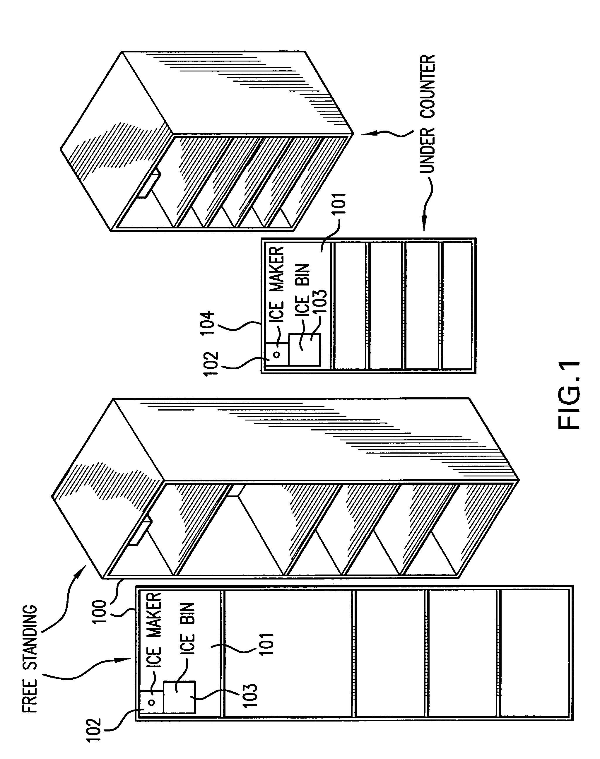
[0027]FIG. 1 shows a standard icemaker 102 located in a standard freezer section 101 of a refrigerator 100. Ice bin 103 positioned under icemaker 102 is provided to receive harvested ice. In different embodiments, the icemaker may be installed in but not limited to the freezer section of a side by side refrigerator or bottom mount refrigerator (a refrigerator with freezer section located in the drawer). It is contemplated that the present invention may also be practiced in other types of refrigerators, such as undercounter refrigerator 104 as well as icemaking machines. A further unique application of the invention is that it may be installed in the “fresh food” or “refrigerated” section of a refrigerator.

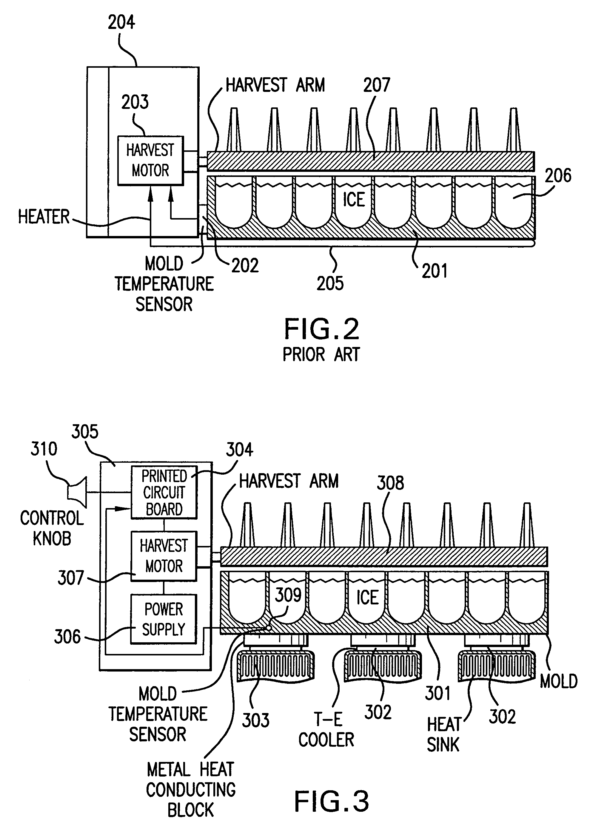
[0028]FIG. 2 is a schematic elevational cross section of a typical prior art icemaker. Metal mold 201 is provided for holding water 206 and creating the shape of the ice cube. A time-metered amount of water is introduced into mold 201 and the liquid flows through channels located b...


PUM


Abstract

The icemaker presented here may use a microcontroller, and solid state refrigeration and heat transfer elements to create ice cube qualities ranging from “clear ice” to “fast ice” in a smooth, user selectable continuum. In one embodiment, this may be accomplished by fitting a standard, high production volume icemaker mold with (1) thermoelectric coolers operated in a controlled fashion to heat or cool the mold, (2) a mold temperature sensor (such as a thermistor), and (3) a microcontroller to monitor the process and to adjust the growth rate of ice forming in the mold by adjusting heat transfer rates to optimize particular cooling phases.

Description

CROSS-REFERENCE TO RELATED APPLICATION[0001]The benefit of the filing date of U.S. Provisional Application No. 60 / 439,620, filed Jan. 14, 2003, and entitled “Variable Rate and Clarity Icemaking Apparatus”, is hereby claimed, and the specification thereof is incorporated herein in its entirety by this reference.BACKGROUND OF THE INVENTION[0002]1. Field of the Invention[0003]This invention generally relates to an automatic icemaker, and more specifically to an improved icemaker for creating ice cubes in a user selectable continuum of qualities which may be judged to be between either “fast” in freezing rate or “clear” in appearance, or some combination thereof.[0004]2. Description of the Related Art[0005]The typical icemaker found in the kitchen refrigerator is located in the freezer section of the appliance. In its simplest form, water is introduced into a mold, frozen, and then harvested into a container positioned beneath the mold. In more complicated systems, ice is made in a mold...

Claims


Application Information

Patent Timeline
IPC IPC(8): F25B21/02F25B21/04F25C1/10
CPCF25B21/04F25C1/10F25B2321/0212
Inventor ADAMSKI, JOSEPH
Owner ADAMSKI JOSEPH R
Learn More