Method for cooling a motor in a blower assembly for a furnance

a technology of blower assembly and furnace, which is applied in the direction of lighting and heating apparatus, domestic stoves or ranges, and ways, etc., can solve the problems of shortening the working life of electronics, reducing the efficiency of motors, and inevitably dragging the fan on the operating motor, so as to reduce the overall length of the assembly and reduce nois

Inactive Publication Date: 2005-10-04
REGAL BELOIT AMERICA
View PDF38 Cites 28 Cited by
  • Summary
  • Abstract
  • Description
  • Claims
  • Application Information

AI Technical Summary

Benefits of technology

[0013]The new method eliminates the need for an auxiliary fan to cool the motor, thereby, reducing the overall length of the assembly. This method not only provides a motor case

Problems solved by technology

The inevitable exposure of the electronics to the vestibule heat shortens the working life of the electronics.
There are three notable drawbacks associated with the presence and operation of fans in a blower motor assembly.
First, the fan inevitably creates drag on the operating

Method used


Image

  • Method for cooling a motor in a blower assembly for a furnance
  • Method for cooling a motor in a blower assembly for a furnance
  • Method for cooling a motor in a blower assembly for a furnance

Examples


Embodiment Construction

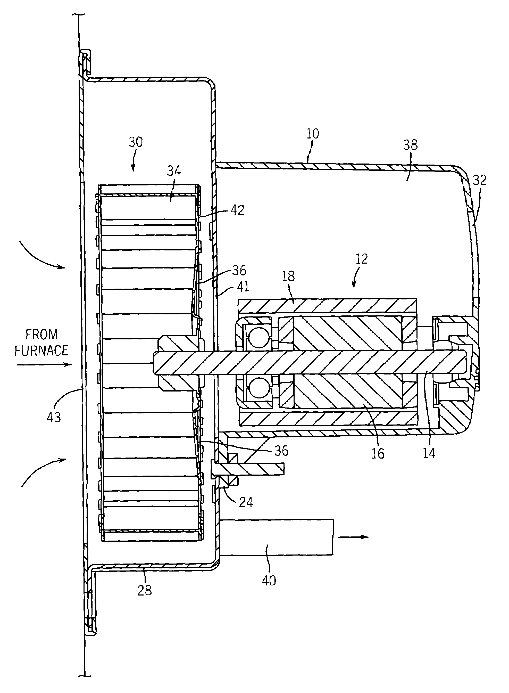
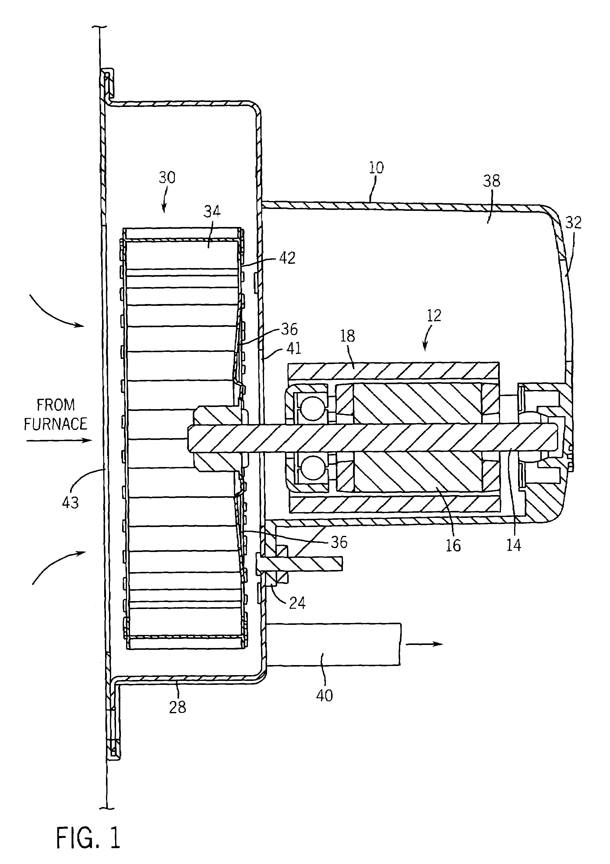
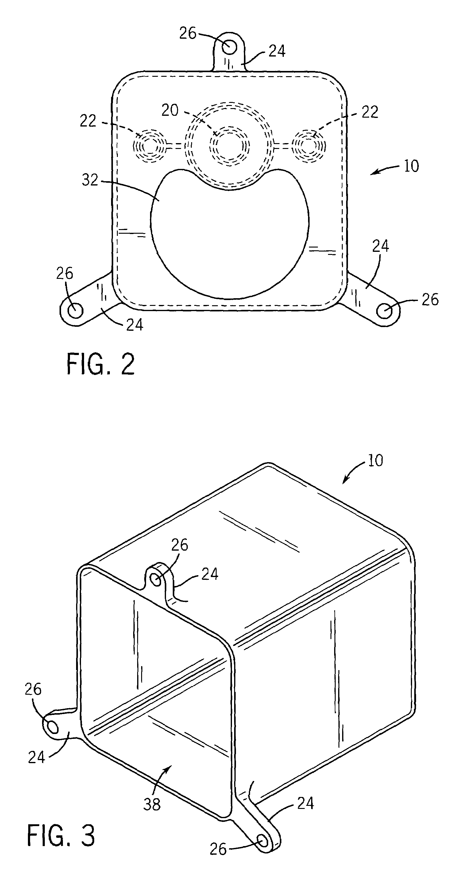
[0018]Referring to FIGS. 1–3, a method for cooling a motor in a blower housing assembly for furnaces according to one embodiment of the invention is shown. A motor cover or housing 10 is configured to encompass a motor 12 which comprises a shaft 14, rotor 16 and stator 18. Motor cover 10 has portions that define a shaft bushing 20 and mechanical fastener bores 22 for securing motor 12 to motor cover 10. Motor cover 10 has flanges 24 each of which has portions defining a fastener bore 26 for securing motor cover 10 to an impeller housing 28 which is configured to encompass an impeller 30 which is attached to shaft 14. Impeller 30 is situated in impeller housing 28 such that impeller 30 can freely rotate within said impeller housing 28.

[0019]Motor cover 10 has at least one hole or aperture 32 located anywhere on motor cover 10 for drawing in air to cool the bearings (not shown) of the motor 12 in the motor cover 10. In an alternate embodiment, vent aperture 32 can be formed as a plura...


PUM


Abstract

A method of cooling the bearings of a motor in a motor housing for a furnace assembly is disclosed comprising an aperture in the motor housing whereby air is brought into the motor housing and drawn around the motor via an impeller into the impeller housing thereby eliminating the need of a separately attached fan to cool the motor or motor bearings. The impeller pulls the air from the motor housing into the impeller housing or blower via an inlet port in the impeller housing and apertures in the back plate of the impeller and out an exhaust port situated in the impeller housing.

Description

CROSS-REFERENCE TO RELATED APPLICATIONS[0001]A claim of benefit is made to U.S. Provision Application Ser. No. 60 / 140,144 filed Jun. 21, 1999, the contents of which are incorporated herein by reference. This application is a continuation of the provisional application Ser. No. 60 / 140,144 entitled, “80+ Blower and Furnace Venting Method” and filed Jun. 21, 1999, the teachings of which are incorporated herein by reference.STATEMENT OF GOVERNMENT INTEREST[0002]Not Applicable.BACKGROUND OF THE INVENTION[0003](1) Field of the Invention[0004]This invention relates generally to a method for cooling a motor in a blower assembly for a furnace. More particularly, the present invention relates to a method of cooling an electric motor without an auxiliary fan in a blower assembly.[0005](2) Description of Related Art[0006]Typically, many gas-furnaces use induced draft blower assemblies to control flue gas by removing the burnt by-products. These blowers are designed to produce a certain amount o...

Claims


Application Information

Patent Timeline
IPC IPC(8): F24H3/00F04D25/08F23L17/00
CPCF04D25/082F23L17/005F04D29/5806
Inventor GATLEY, WILLIAM S.
Owner REGAL BELOIT AMERICA
Why Eureka
Try Eureka