Method and device for controlling the drive unit of a vehicle

a technology for driving units and driving devices, applied in electric control, road transportation, instruments, etc., to achieve the effect of increasing driving comfort, increasing driving comfort, and particularly easy implementation

Inactive Publication Date: 2005-10-04
ROBERT BOSCH GMBH
View PDF4 Cites 58 Cited by
  • Summary
  • Abstract
  • Description
  • Claims
  • Application Information

AI Technical Summary

Benefits of technology

[0006]An exemplary embodiment of the present invention for controlling the drive unit of a vehicle, may provide that an output variable of the drive unit, such as a torque or a vehicle speed, is set to a constant value during the transition between engaged-clutch travel mode and free-wheel mode. This may avoid unwanted accelerations and decelerations during the transition between engaged-clutch travel mode and free-wheel mode, thus making the transition smoother.
[0007]In an example embodiment of the present invention, the constant value is set for the output variable by coordinating clutch intervention and engagement of a vehicle brake. This may make it possible to avoid the above-mentioned decelerations and accelerations during the transition between engaged-clutch travel mode and free-wheel mode with particular ease and safety.
[0008]In an example embodiment of the present invention, the constant value is set for the output variable via a regulator. This may make it possible to set the constant value for the output variable within a very narrow tolerance.

Problems solved by technology

In addition, free-wheel transmissions are believed to be conventional which do not have this disadvantage since they transmit the engine torque only in driving mode, but do not transmit the engine braking torque in overrun mode.
However, the vehicle must always be decelerated by the vehicle brake, which can overheat, in particular, during long downhill travel.

Method used


Image

  • Method and device for controlling the drive unit of a vehicle
  • Method and device for controlling the drive unit of a vehicle
  • Method and device for controlling the drive unit of a vehicle

Examples


Embodiment Construction

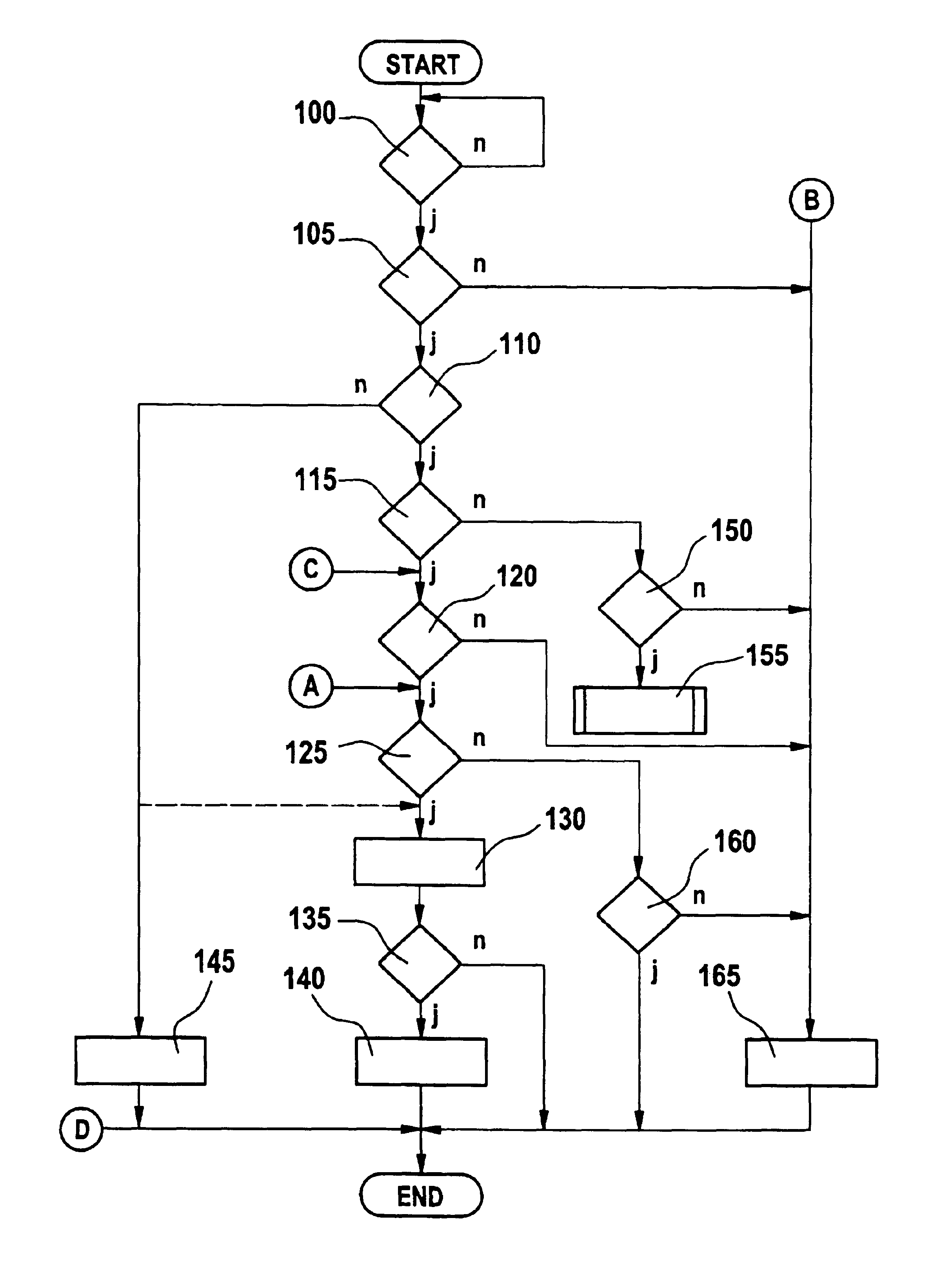
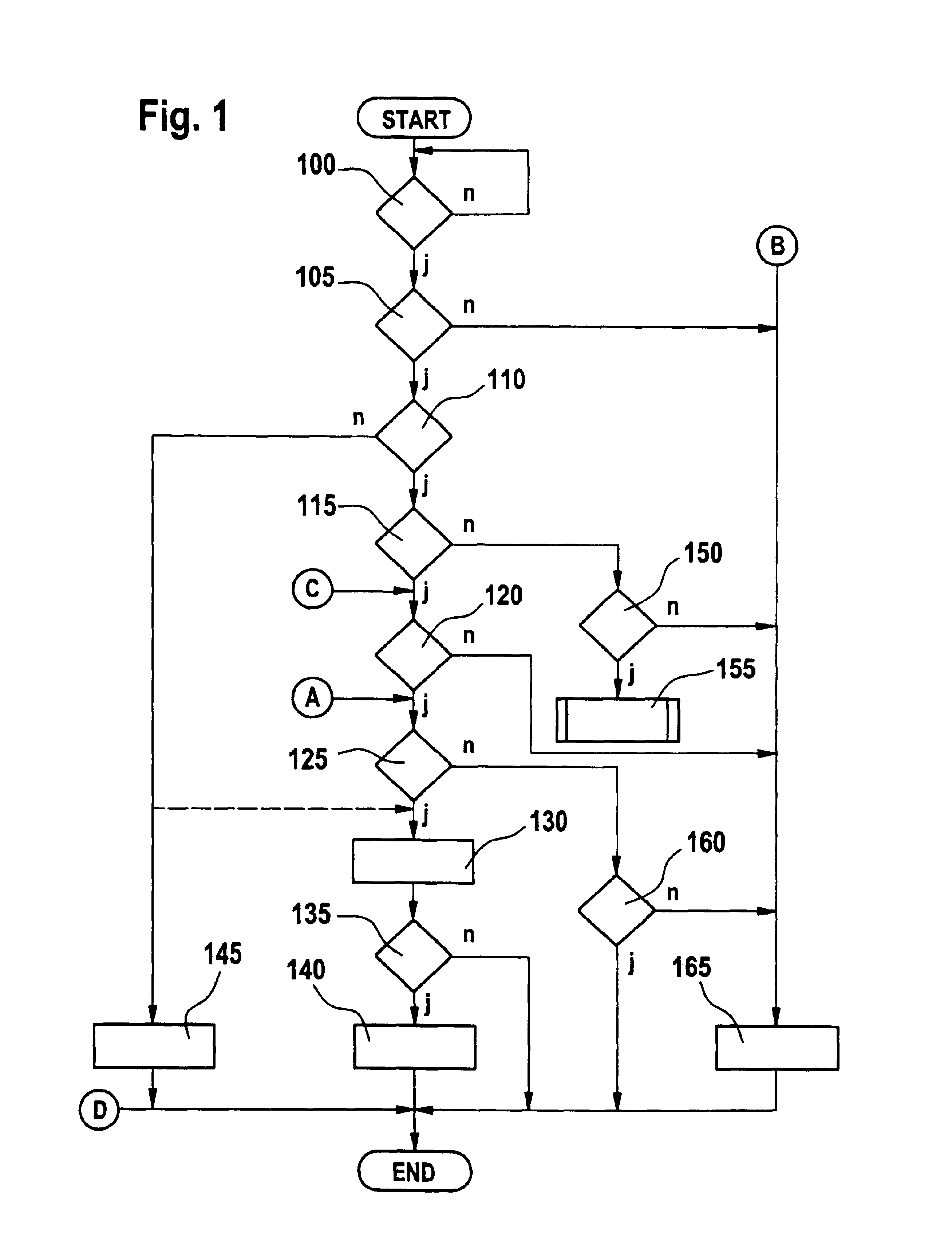
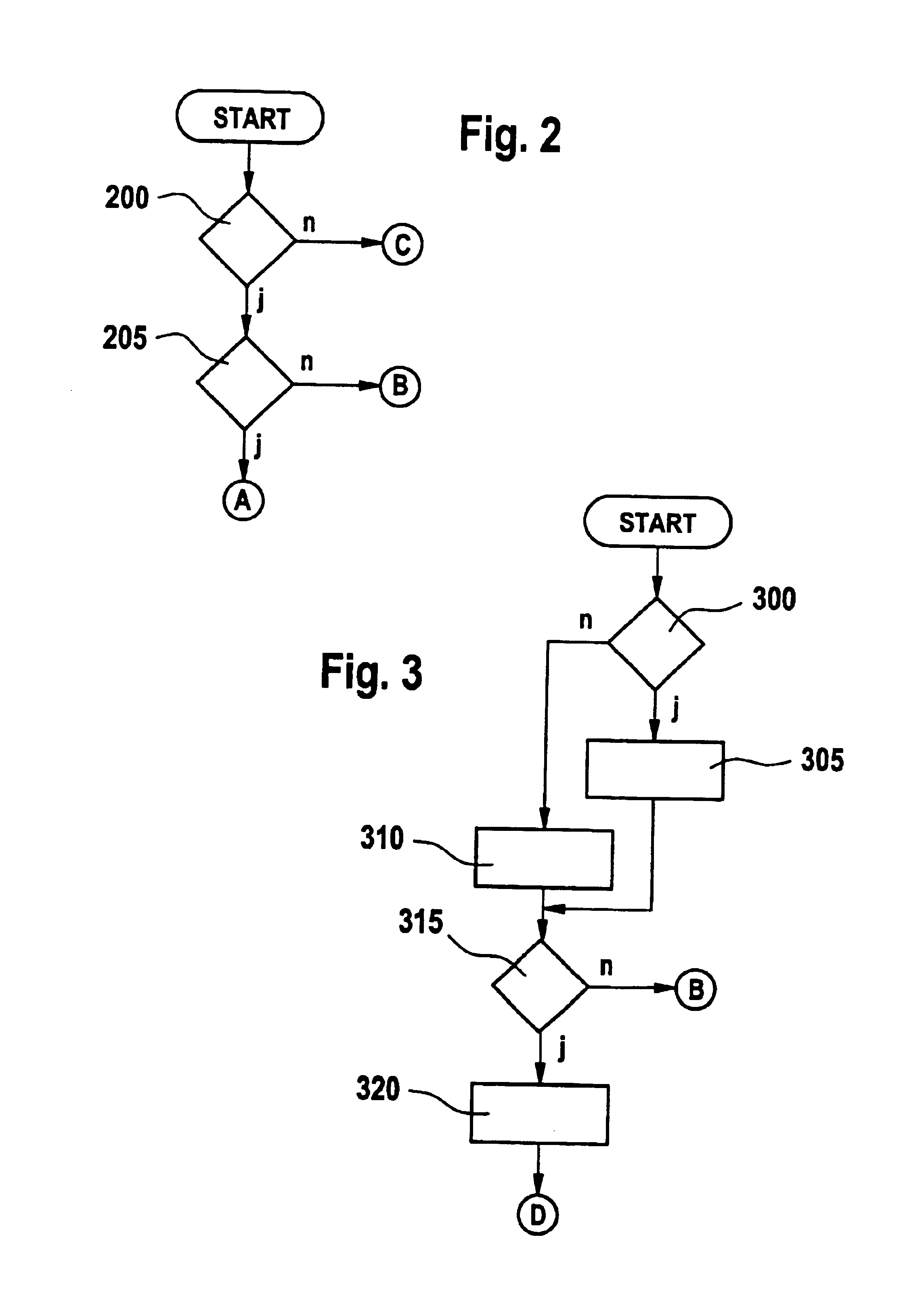
[0025]The method according to an example embodiment of the present invention may be implemented, for example, in an engine control unit, a transmission control unit and / or a clutch control unit of a vehicle, for example, in the form of a computer program. According to this exemplary embodiment, the vehicle is provided, for example, with an internal combustion engine. During vehicle operation, driving situations arise in which the vehicle engine does not perform a driving action, but rather acts in a more or less braking fashion in an overrun mode. In this overrun mode, an engine braking torque is transmitted from the rotating driving wheels to the engine via the transmission and clutch. Overrun mode occurs, in particular, when the driver removes his foot from the accelerator. However, this does not always mean that the driver wishes to actually brake the vehicle using the engine braking torque, i.e., the engine brake. According to an example embodiment of the present invention, the ...


PUM


Abstract

A method for controlling the drive unit of a vehicle in which an extended overrun mode having reduced fuel consumption and reduced pollutant emission is possible. A free-wheel mode in which the vehicle operates with the clutch disengaged is set as a function of a driving situation or an operating state of the drive unit. An output variable of the drive unit, such as torque or vehicle speed, is set to a constant value during the transition between an engaged-clutch travel mode and a free-wheel mode.

Description

CROSS-REFERENCE TO RELATED APPLICATIONS[0001]The present application claims priority to Application No. 103 07 462.7, filed in the Federal Republic of Germany on Feb. 21, 2003, which is expressly incorporated herein in its entirety by reference thereto.FIELD OF THE INVENTION[0002]The present invention relates to a method and a device for controlling the drive unit of a vehicle.BACKGROUND INFORMATION[0003]In some vehicles, it is possible to use a control unit to electrically operate the clutch if the vehicle is equipped with an automated transmission or an enhanced transmission. In an overrun mode, the clutch between the engine and transmission is engaged, which brakes the vehicle due to the compressor action of the engine and friction. In addition, free-wheel transmissions are believed to be conventional which do not have this disadvantage since they transmit the engine torque only in driving mode, but do not transmit the engine braking torque in overrun mode. However, the vehicle m...

Claims


Application Information

Patent Timeline
Patent Type & Authority Patents(United States)
IPC IPC(8): B60K31/00F02D41/02F02D45/00B60W10/02B60W10/04B60W10/18B60W30/18F02D29/00F02D29/02F02D41/04F02D41/28F16D48/06
CPCB60K31/00B60W10/02B60W10/04B60W10/184B60W30/18018B60W30/18072B60W30/1882Y10T477/6392B60K2741/245B60L2240/441B60L2240/486B60W2030/1809B60W2510/0638B60W2530/10B60W2550/142B60W2710/0644B60W2710/105F02D41/021F02N11/0818Y02T10/56Y02T10/48Y10T477/6388B60K2741/025B60W10/18B60W30/1819Y02T10/84B60W2552/15Y02T10/40Y02T10/60
Inventor RIES-MUELLER, KLAUS
Owner ROBERT BOSCH GMBH
Why Eureka
Try Eureka