
Method for operating a motor-driven vehicle

a technology for motor vehicles and parking brakes, which is applied in the direction of brake action initiation, brake systems, mechanical devices, etc., can solve the problems of critical situations impairing safety, damage to the braking system of the motor vehicle, etc., and achieve the effect of high reliability

Inactive Publication Date: 2005-10-04
CONTI TEMIC MICROELECTRONIC GMBH
View PDF20 Cites 23 Cited by
  • Summary
  • Abstract
  • Description
  • Claims
  • Application Information

AI Technical Summary

Benefits of technology

[0004]The underlying object of the invention is to propose a simple method for operating a motor-driven motor vehicle with a high reliability and safety.
[0030]The basic informations underlying the method can be obtained in a simple manner, especially by means of sensors already present in the motor vehicle, so that driving with a set or applied parking brake can advantageously be prevented in a simple and cost-effective or economical manner, without the operator of the motor vehicle having to be bothered by or pay attention to this, and without the parking brake being unintentionally released. Thereby, a method that increases the safety in the driving traffic can thus be realized.

Problems solved by technology

When again beginning to drive the motor vehicle, the releasing of the set parking brake can be forgotten by the operator of the motor vehicle; the driving with a set or applied parking brake can, however, lead to an impairment or damage of the braking system of the motor vehicle.
With this information by itself, a driving of the motor vehicle is often erroneously assumed, even in connection with an undesired and unintended rolling of the vehicle (for example due to diminishing or slackening braking force or insufficient setting or applying of the parking brake), whereby critical situations impairing the safety can arise.

Method used


Image

  • Method for operating a motor-driven vehicle
  • Method for operating a motor-driven vehicle

Examples


Embodiment Construction

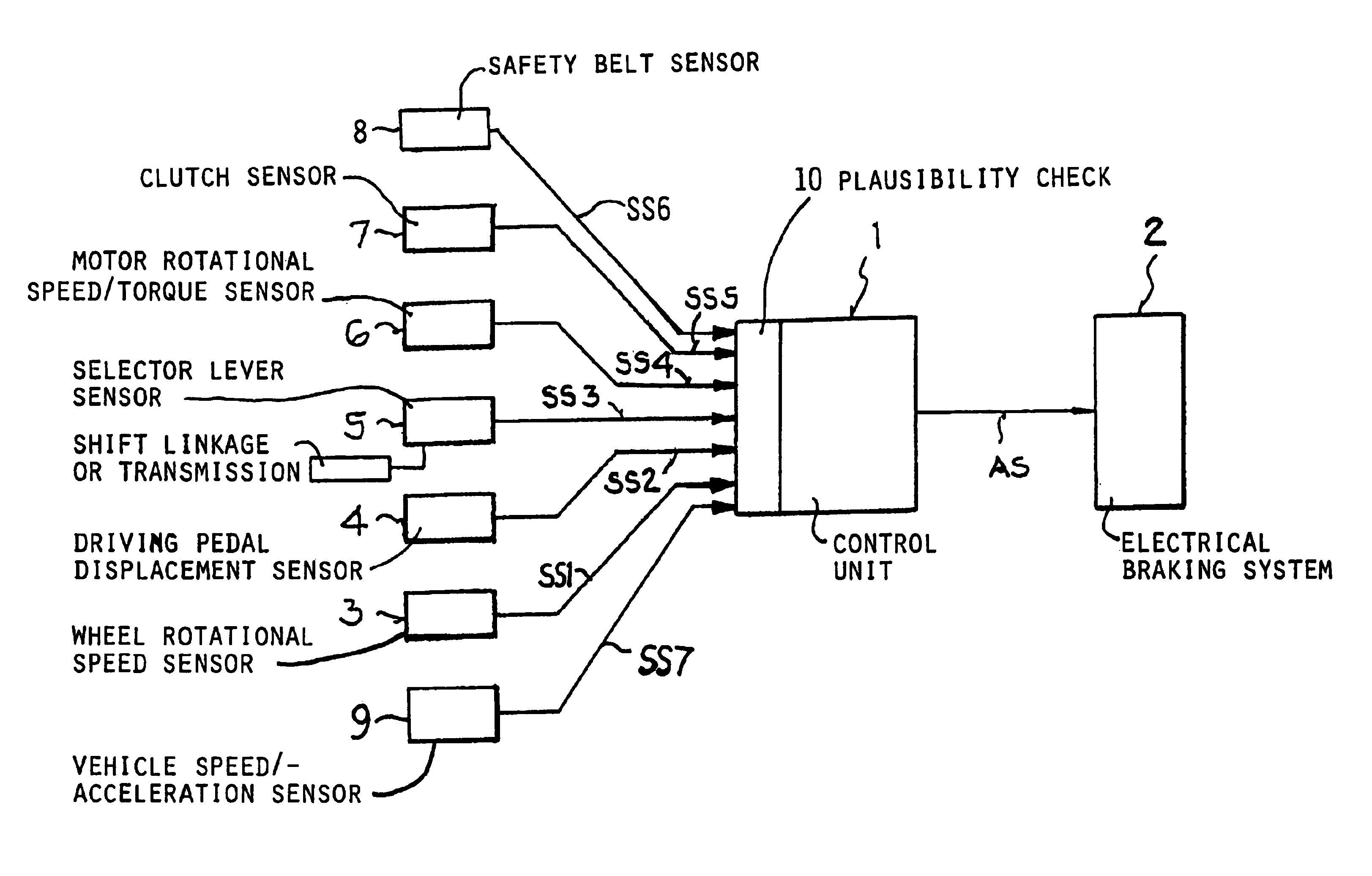
[0032]According to the Figure, a control unit 1 (logic unit) is provided in the motor vehicle, to which control unit 1, sensor signals SS1, SS2, SS3, SS4, SS5, SS6 and SS7 of plural sensors 3, 4, 5, 6, 7, 8 and 9 (that is to say the measured values acquired from the sensors 3, 4, 5, 6, 7, 8 and 9) are delivered as input signals, and which, dependent on the sensor signals SS1, SS2, SS3, SS4, SS5, SS6, and SS7, actuates the electrical braking system 2 of the motor vehicle with an output signal AS (control signal) generated therefrom (for example by acting on the brake actuator for prescribing a specific braking force). The sensor signals SS1, SS2, SS3, SS4, SS5, SS6 and SS7 provide, as measured values, information on the one hand regarding the motion of the motor vehicle (and especially also regarding the speed of the motor vehicle in the motion), on the other hand regarding the desire of the operator of the motor vehicle (the driver's desire) for movement of the motor vehicle. As a s...


PUM


Abstract

To avoid damaging the electrical braking system of a motor vehicle due to driving with an applied parking brake, the parking brake is automatically released, if the speed of the motor vehicle exceeds a prescribed minimum value, and the drive unit of the motor vehicle is driven in a specific operating state, and at least one operating element (e.g. gas pedal, gear shift lever, clutch pedal, safety belt, etc.) of the motor vehicle has been actuated by the driver of the motor vehicle. Sensor signals of sensors that sense the state of the above parameters are subjected to a plausibility check.

Description

FIELD OF THE INVENTION[0001]The invention relates to a method of controlling a parking brake of a motor vehicle.BACKGROUND INFORMATION[0002]In motor-driven vehicles, a parking brake is generally provided for arresting or fixing the motor vehicle at a standstill and especially in connection with the parking of the motor vehicle. When again beginning to drive the motor vehicle, the releasing of the set parking brake can be forgotten by the operator of the motor vehicle; the driving with a set or applied parking brake can, however, lead to an impairment or damage of the braking system of the motor vehicle. As a result, driving with a set or applied parking brake should be avoided.[0003]From the German Patent Publication DE 198 14 657 A1 with a control and / or regulating arrangement for an electrical parking brake arrangement of motor vehicles, forming the general background of this art, it is known to provide a sensor unit for measuring the wheel rotational speed of the vehicle, by mean...

Claims


Application Information

Patent Timeline
IPC IPC(8): B60T7/02B60T7/10B60T13/74B60T13/00B60T7/04
CPCB60T7/045B60T7/107B60T13/741Y10T477/86Y10T477/847Y10T477/83Y10S477/906
Inventor EWINGER, HEINZFARRENKOPF, ARMINGROTH, JUERGENJUST, THOMAS
Owner CONTI TEMIC MICROELECTRONIC GMBH
Learn More