Dynamic flying attitude control using augmented gimbal

Inactive Publication Date: 2005-10-04
SEAGATE TECH LLC
View PDF35 Cites 45 Cited by
  • Summary
  • Abstract
  • Description
  • Claims
  • Application Information

AI Technical Summary

Benefits of technology

[0023]The present invention is a head suspension for a head assembly in a disc drive. The head suspension includes controllable bending elements on the gimbal portion of the head suspension which allow dynamic control of the flying attitude of the head assemblies, and thus the flying height. In a first embodiment, the control elements are bi-metal features that utilize differential thermal expansion to control the flying attitude.

Problems solved by technology

With such discs, the size of the magnetic domain required to record a flux transition was clearly limited by the average size of the oxide particles and how closely these oxide particles were spaced within the adhesive matrix.
The smoothness and flatness of the disc surface was also similarly limited.
As the surfaces of the discs has become progressively smoother—in order to increase areal recording density, as noted above—it

Method used


Image

  • Dynamic flying attitude control using augmented gimbal
  • Dynamic flying attitude control using augmented gimbal
  • Dynamic flying attitude control using augmented gimbal

Examples


Embodiment Construction

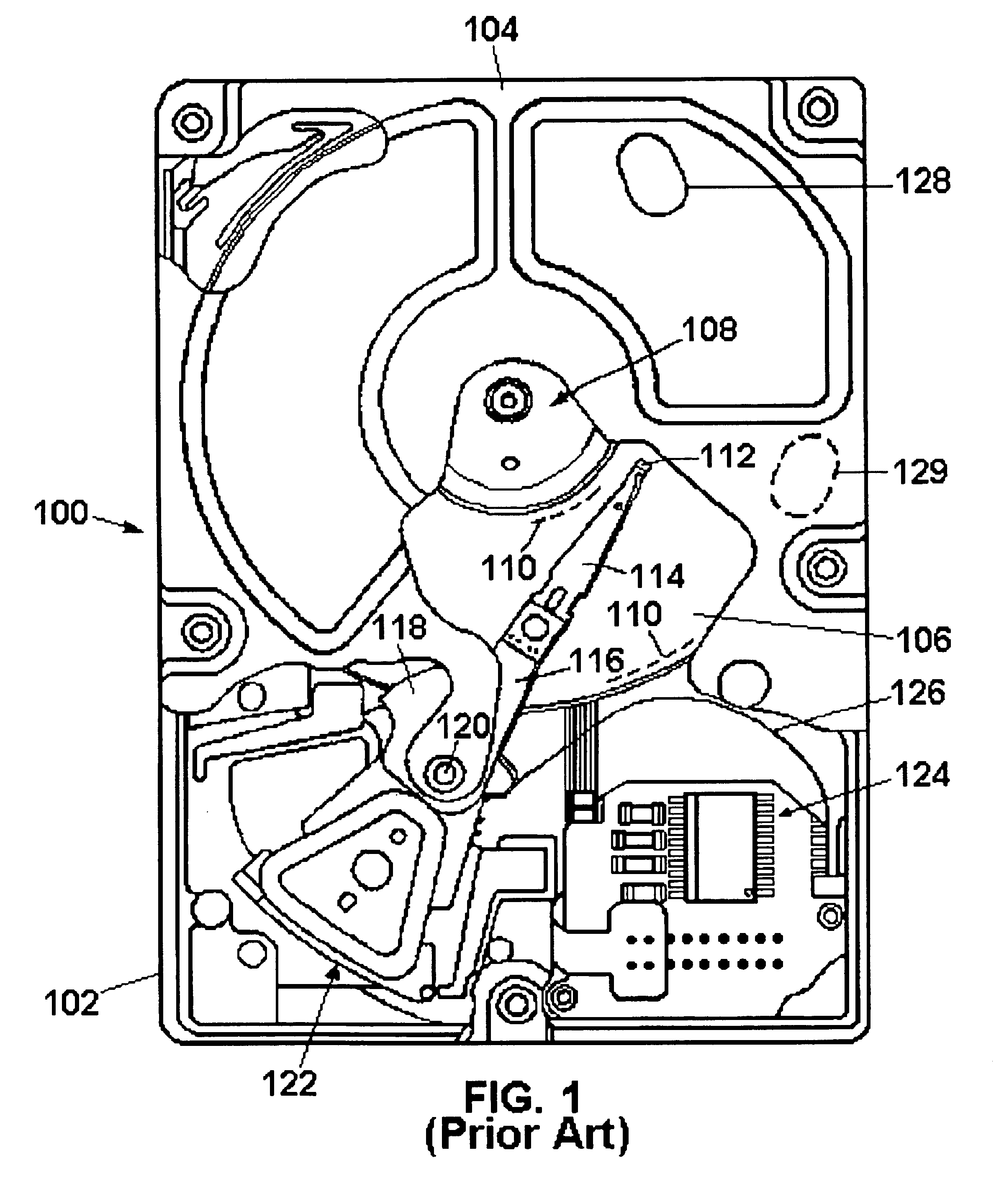
[0042]Turning now to the drawings and specifically to FIG. 1, shown is a plan view of a disc drive 100 with which the present invention is particularly useful. The disc drive 100 includes a base member 102 to which all other components are directly or indirectly mounted and a top cover 104 (shown in partial cutaway) which, together with the base member 102, forms a disc drive housing which encloses delicate internal components and isolates these components from external contaminants.

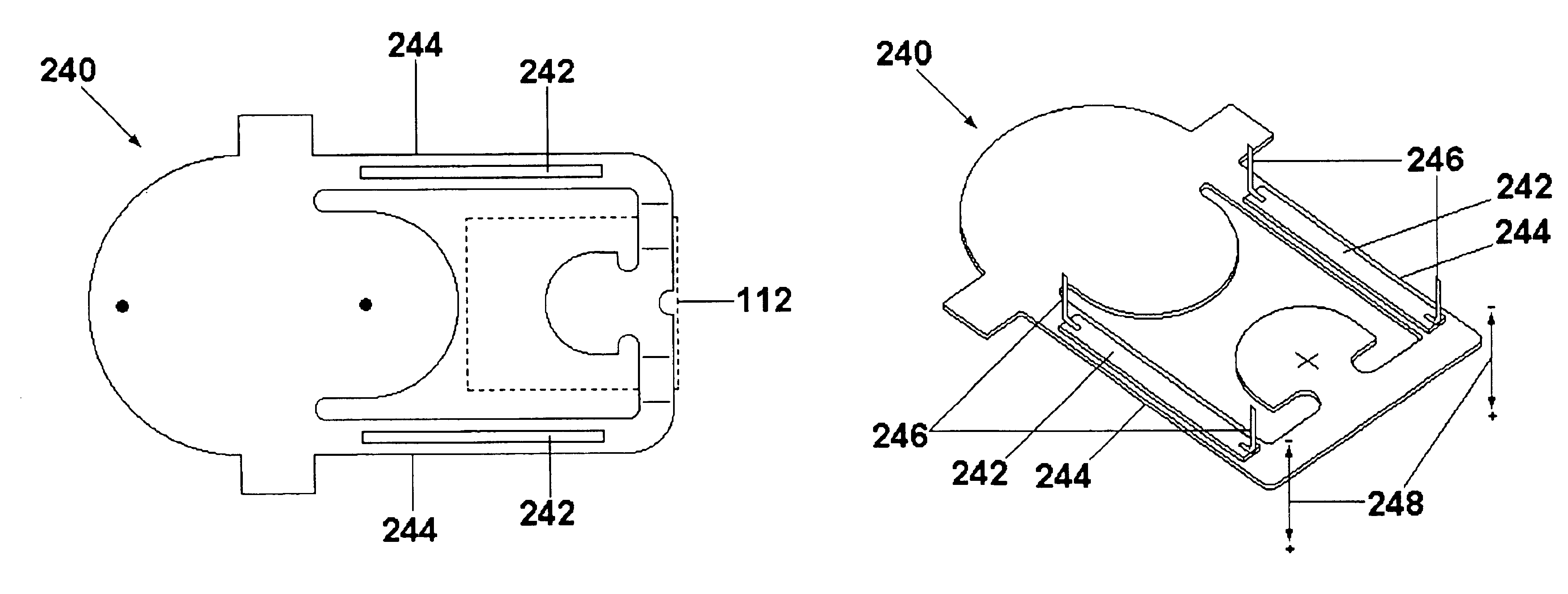
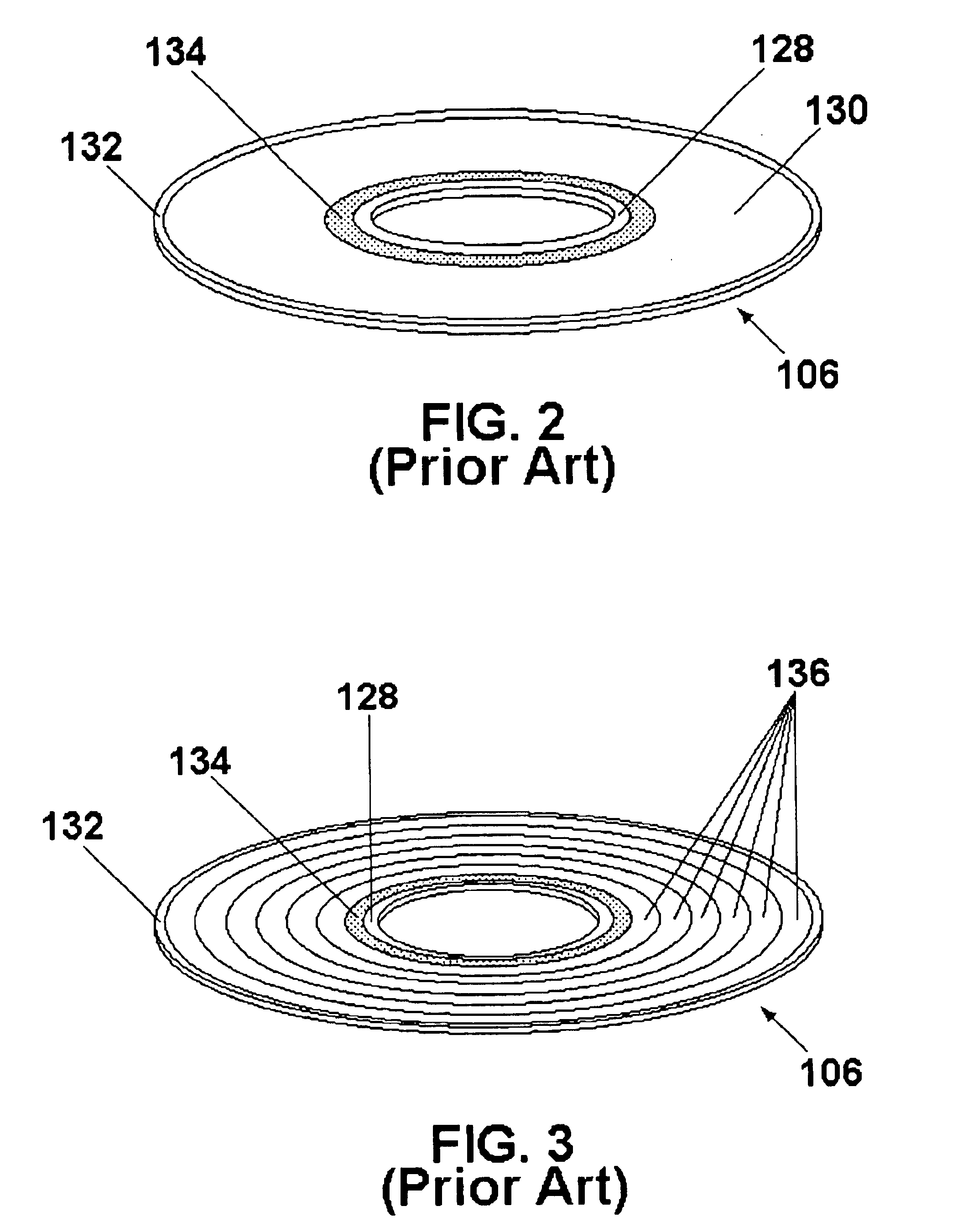
[0043]The disc drive includes a plurality of discs 106 which are mounted for rotation on a spindle motor shown generally at 108. The discs 106 include on their surfaces a plurality of circular, concentric data tracks, the innermost and outermost of which are shown by dashed lines at 110, on which data are recorded via an array of vertically aligned head assemblies (one of which is shown at 112). The head assemblies 112 are supported by head suspensions, or flexures 114, which are attached to actuator hea...


PUM


Abstract

A head suspension mounts a head assembly in a disc drive. The head suspension includes controllable bending elements on the gimbal portion of the head suspension which allow dynamic control of the flying attitude of the head assemblies, and thus the flying height. In a first embodiment, the control elements are bi-metal features that utilize differential thermal expansion to control the flying attitude. In a second, and presently preferred, embodiment, the control elements are piezo-electric elements which provide bi-directional control of associated elements of the gimbal portion of the head suspension. In another aspect, the controllable bending elements are used to increase the flying height of the head assembly as the head assembly is moved from the data recording area of the disc into engagement with a textured landing zone.

Description

CROSS REFERENCE TO RELATED APPLICATION[0001]This application claims the benefit of U.S. Provisional Application Ser. No. 60 / 138,691, filed Jun. 11, 1999.BACKGROUND OF THE INVENTION[0002]This application relates generally to the field of rigid magnetic disc drive data storage devices, and more particularly, but not by way of limitation, to a head suspension for mounting and supporting a head assembly in a disc drive, and for providing dynamic control of the flying attitude of the head assembly.[0003]Disc drives of the type known as “Winchester” disc drives or rigid disc drives are well known in the industry. Such disc drives magnetically record digital data on a plurality of circular, concentric data tracks on the surfaces of one or more rigid discs. The discs are typically mounted for rotation on the hub of a brushless DC spindle motor. In disc drives of the current generation, the spindle motor rotates the discs at speeds of up to 15,000 RPM.[0004]Data are recorded to and retrieved...

Claims


Application Information

Patent Timeline
IPC IPC(8): G11B21/21G11B5/48G11B5/58G11B5/60
CPCG11B5/4826G11B5/58G11B5/6005G11B5/4833
Inventor RIDDERING, JASON WAYNEMANGOLD, MARKUS ERWINBOUTAGHOU, ZINE-EDDINE
Owner SEAGATE TECH LLC
Why Eureka
Try Eureka