Friction stir welding apparatus of piston for swash plate type compressor with variable capacity

a technology of swash plate type compressor and friction stir welding, which is applied in the direction of soldering apparatus, positive displacement liquid engine, auxillary welding device, etc., can solve the problems of deteriorating compression efficiency, defective rate becoming too high, and affecting the service life of the compressor, so as to prevent the lowering of the durability of the welded portion

Inactive Publication Date: 2005-10-11
HANON SYST
View PDF12 Cites 23 Cited by
  • Summary
  • Abstract
  • Description
  • Claims
  • Application Information

AI Technical Summary

Benefits of technology

[0018]Accordingly, the present invention has been made in view of the above described problems, and an object of the present invention is to provide a friction stir welding apparatus of a piston for a swash plate type compressor with variable capacity, which prevents formation of a hole in a welded portion between two piston members, which are coupled integrally to each other by friction stir welding, thereby preventing lowering of durability of the welded portions during a coating process and an abrasion process after the friction stir welding.
[0019]Another object of the present invention is to provide a friction stir welding apparatus of a piston for a swash plate type compressor with variable capacity, which can easily bond the piston members with each other regardless of the outer diameter size of the piston members.

Problems solved by technology

In such a swash plate type compressor with variable capacity, weight of the piston acts as inertia preventing reciprocating motion of the piston during a refrigerant compressing process, thereby deteriorating compression efficiency.
However, the conventional hollow piston manufacturing method has several problems in that it is necessary to process the coupled surfaces precisely, that it takes too much time to assemble the first and second piston members, and that it is complex and difficult to process the first and second piston members, so that its productivity is deteriorated, and defective rate becomes too high.
Furthermore, the conventional hollow piston manufacturing method has another problem in that durability of the piston is lowered as fine holes are formed inside the piston during the electron beam welding step.
The conventional hollow piston manufacturing method has a further problem in that refrigerant and oil are run short because the refrigerant and oil permeate inside the hollow portion through the fine holes.
Particularly, the conventional hollow piston manufacturing method has a problem in that maintenance and manufacturing costs are increased as the welding area of the piston must be kept in a high vacuum condition for the electron beam welding.
However, under the above conventional method, the welding temperature is not uniformly distributed on the joint surface due to a minute difference in flatness of the joint surface as the joint surface is flat, and so, it is difficult to uniformly keep the welding strength of the joint surface.
However, the friction stir butt welding method has a disadvantage in that a hole is formed in the friction portion between the materials by the probe after the friction welding.
As shown in FIG. 8, in manufacturing a piston 1, the friction stir butt welding method has a disadvantage in that it is impossible to form coating film of uniform thickness during a coating process after the friction welding and durability of the welded portion is deteriorated because a hole 5 is formed in a friction portion, i.e., welded portion, between the first piston member 3 having a bridge 2 and the second piston member 4.
When plastic working is performed in this condition, an elevated portion is formed at the position of the hole 5, and so, the coating film is not uniform.
Therefore, an abrasion process can be performed eccentrically, thereby resulting in lowering of durability.
The friction stir butt welding method has other disadvantages in that there is possibility to cause bending deformation on the members by pressure when the probe is inserted into the welded portion between the two members, and so, it is difficult to manufacture the piston, which must have a precise outer diameter.
To manufacture pistons having different outer diameters, it is necessary to change or separately manufacture the welding apparatus according to the outer diameter, thereby increasing the manufacturing costs.

Method used


Image

  • Friction stir welding apparatus of piston for swash plate type compressor with variable capacity
  • Friction stir welding apparatus of piston for swash plate type compressor with variable capacity
  • Friction stir welding apparatus of piston for swash plate type compressor with variable capacity

Examples


Embodiment Construction

[0040]Reference will now be made in detail to the preferred embodiments of the present invention, examples of which are illustrated in the accompanying drawings.

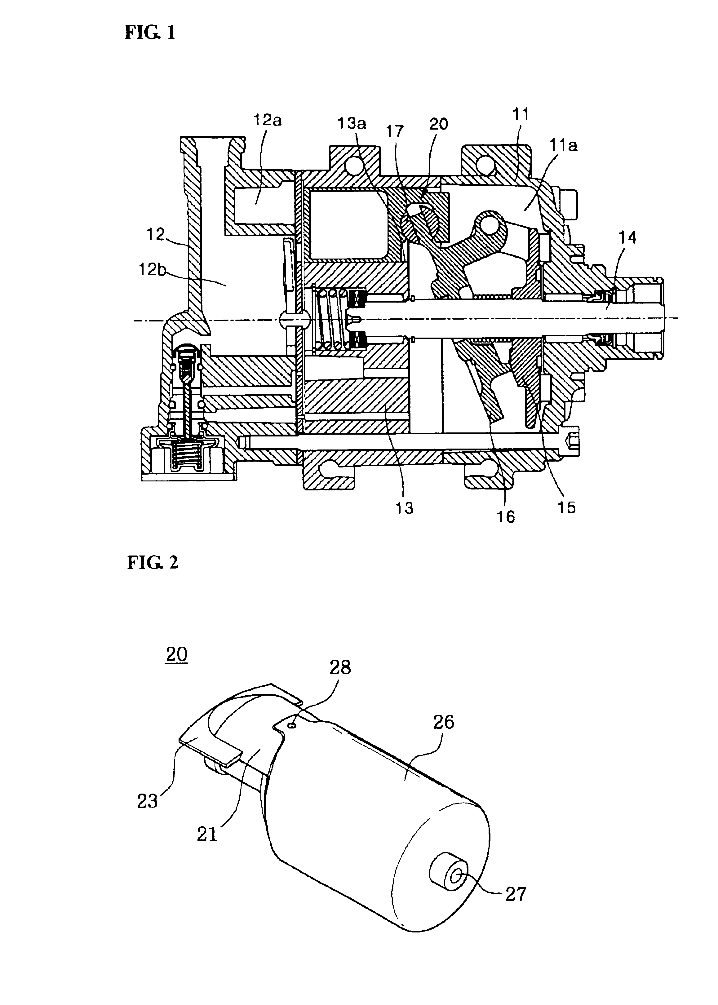
[0041]FIG. 1 briefly shows the structure of a swash plate type compressor with variable capacity, to which a piston according to the present invention is mounted.

[0042]As shown in FIG. 1, the swash plate type compressor includes: front and rear housings 11 and 12 forming sealed spaces therein, such as a crank chamber 11a, a suction chamber 12a, and a discharge chamber 12b; a cylinder block 13 installed between the front and rear housings 11 and 12 and having a number of cylinder bores 13a arranged in the circumferential direction; a driving shaft 14 rotatably mounted on the center of the cylinder block 13 and having a lug plate 15; a swash plate 16 hinged with a side of the lug plate 15 and having a slant angle varied according to cooling load; and a number of pistons 20 connected with shoes 17, which are provided along the ...


PUM

PropertyMeasurementUnit
outer diameteraaaaaaaaaa
heightaaaaaaaaaa
pressureaaaaaaaaaa

Abstract

A friction stir welding apparatus of a piston for variable capacity swash plate type compressor bonds two pistons through frictions stir welding without forming a hole in welded portions of the piston members. The friction stir welding apparatus includes: A support that rotatably supports coaxially coupled first and second pistons. A welder, rotatably inserted into welded portions of the first and second pistons supported on the support, performs friction stir welding along the rotation direction of the first and second pistons. Support rollers elastically mounted on the lower portions of the pistons have central axis lines of the piston members on central axis lines of the rotation support while the pistons are supported on the support. The rollers vertically move through a predetermined height while supporting the pistons. The welder is transferred from the welded portions to another position after welding of the welded portions.

Description

BACKGROUND OF THE INVENTION[0001]1. Field of the Invention[0002]The present invention relates to a friction stir welding apparatus of a piston for a swash plate type compressor with variable capacity. More particularly, the present invention relates to a friction stir welding apparatus of a piston for a swash plate type compressor with variable capacity, which integrally bonds two round sections of piston members through friction stir welding without forming a hole in welded portions of the piston members, thereby improving durability of the welded portions and easily bonding the piston members regardless of the size of the outer diameter of the piston members.[0003]2. Background of the Related Art[0004]In general, a swash plate type compressor with variable capacity of a cooling apparatus of an automobile includes: front and rear housings forming sealed spaces therein, such as a crank chamber, a suction chamber, a discharge chamber, and so on; a cylinder block installed between the...

Claims


Application Information

Patent Timeline
Patent Type & Authority Patents(United States)
IPC IPC(8): B23K20/12F04B27/08
CPCB23K20/122F04B27/0878
Inventor PARK, DAE-KYUKIM, KYOUNG-DUCK
Owner HANON SYST
Why Eureka
Try Eureka