Dive mask system

a mask system and mask technology, applied in the field of masks, can solve the problems of limited flexibility of transparent elastomeric materials, and achieve the effects of low manufacturing cost, easy and efficient manufacturing and marketing, and durable and reliable construction

Inactive Publication Date: 2005-10-11
ICARE INDS
View PDF5 Cites 21 Cited by
  • Summary
  • Abstract
  • Description
  • Claims
  • Application Information

AI Technical Summary

Benefits of technology

[0012]Further provided is a shield assembly. The shield assembly is fabricated of a transparent elastomeric material, such as plastic or rubber, natural or synthetic, or blends thereof. The transparent elastomeric material has limited flexibility. The material is a color selected from magenta and yellow. The shield assembly has a planar front area. The planar front area is positionable in front of the frames and lenses. The shield assembly has a rearwardly extending peripheral ledge. The peripheral ledge is positionable adjacent to the upper and lower horizontal areas. The peripheral ledge is laterally spaced to the vertical areas of the frames. The shield assembly also includes an upper projection. The upper projection extends rearwardly from the shield with a finger extending downwardly adjacent to the upper horizontal area of the frame. Two lower projections extend rearwardly from the shield. Each projection has a finger. The finger extends upwardly adjacent to the lower horizontal area of the frame. The projections and fingers are adapted to releasably couple the shield assembly to the mask assembly. A large rectangular aperture is provided in the planar front area of the shield assembly adjacent to the upper projection. A small rectangular aperture is provided in the planar front area of the shield assembly adjacent to each lower first projection. The apertures function to facilitate the molding of the shield assembly as a unitary component.
[0021]Even still another object of the present invention is to provide a dive mask with optical filter system for maximizing a diver's visibility as a function of the environment.

Problems solved by technology

The transparent elastomeric material has limited flexibility.

Method used


Image

  • Dive mask system
  • Dive mask system
  • Dive mask system

Examples


Embodiment Construction

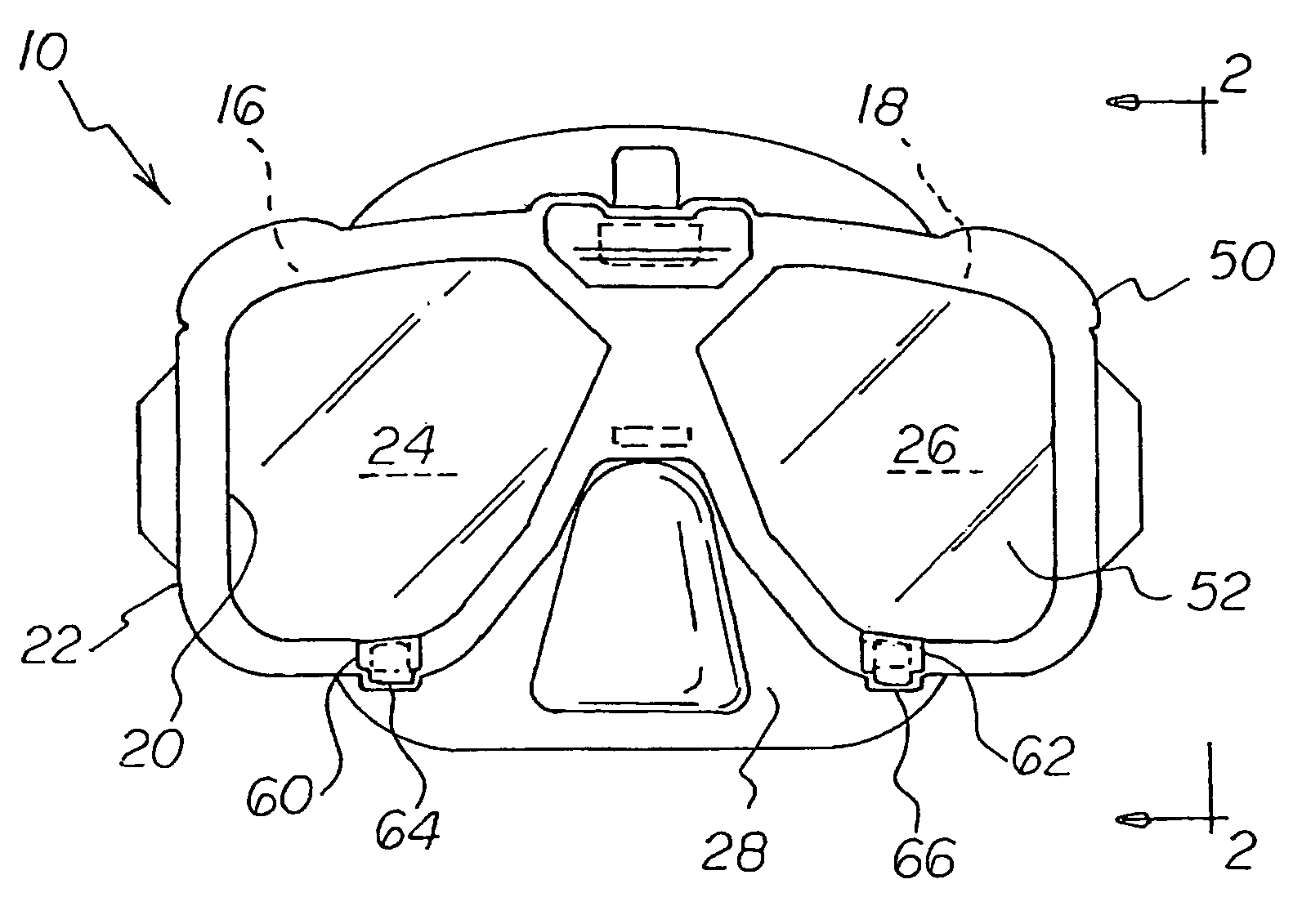
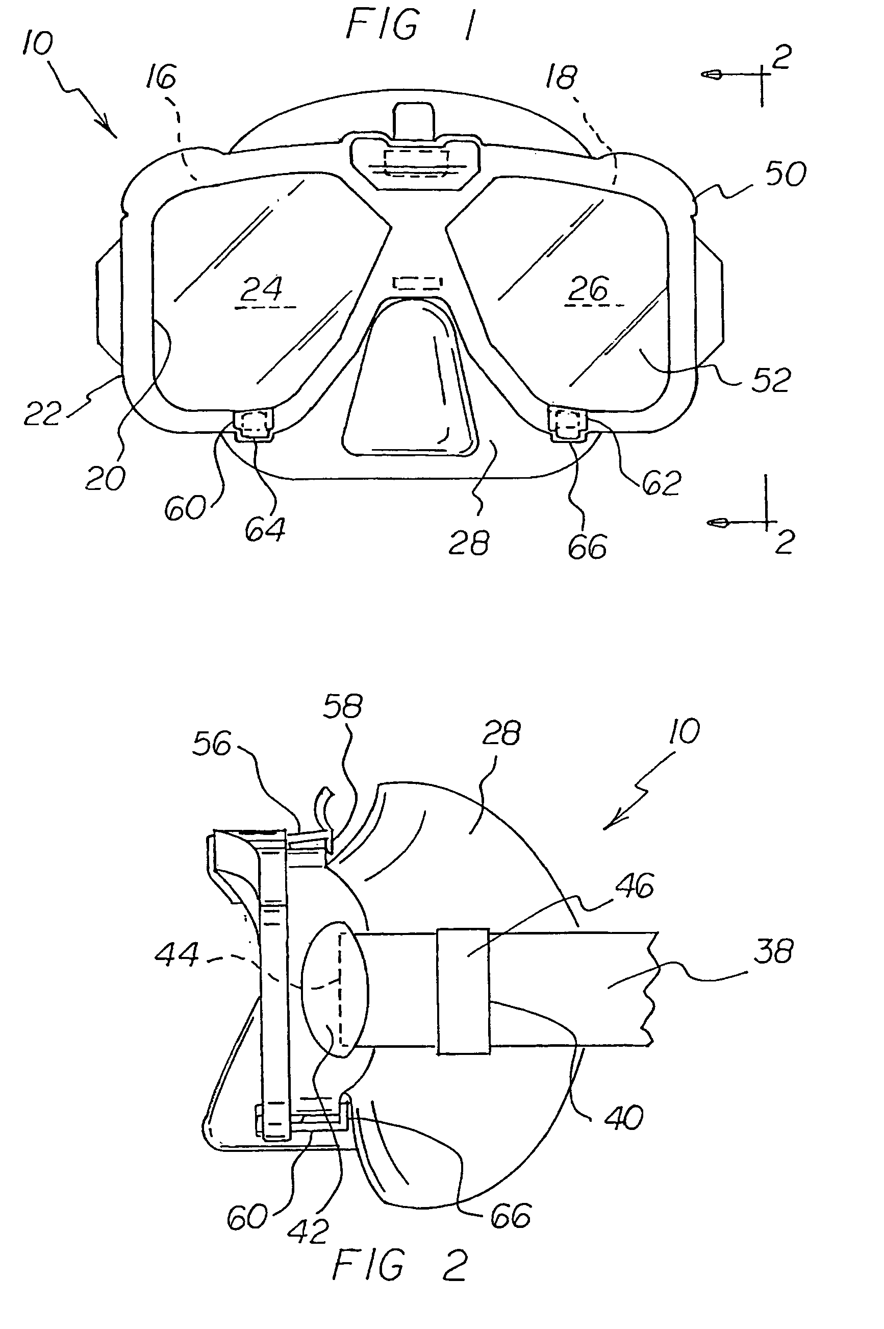
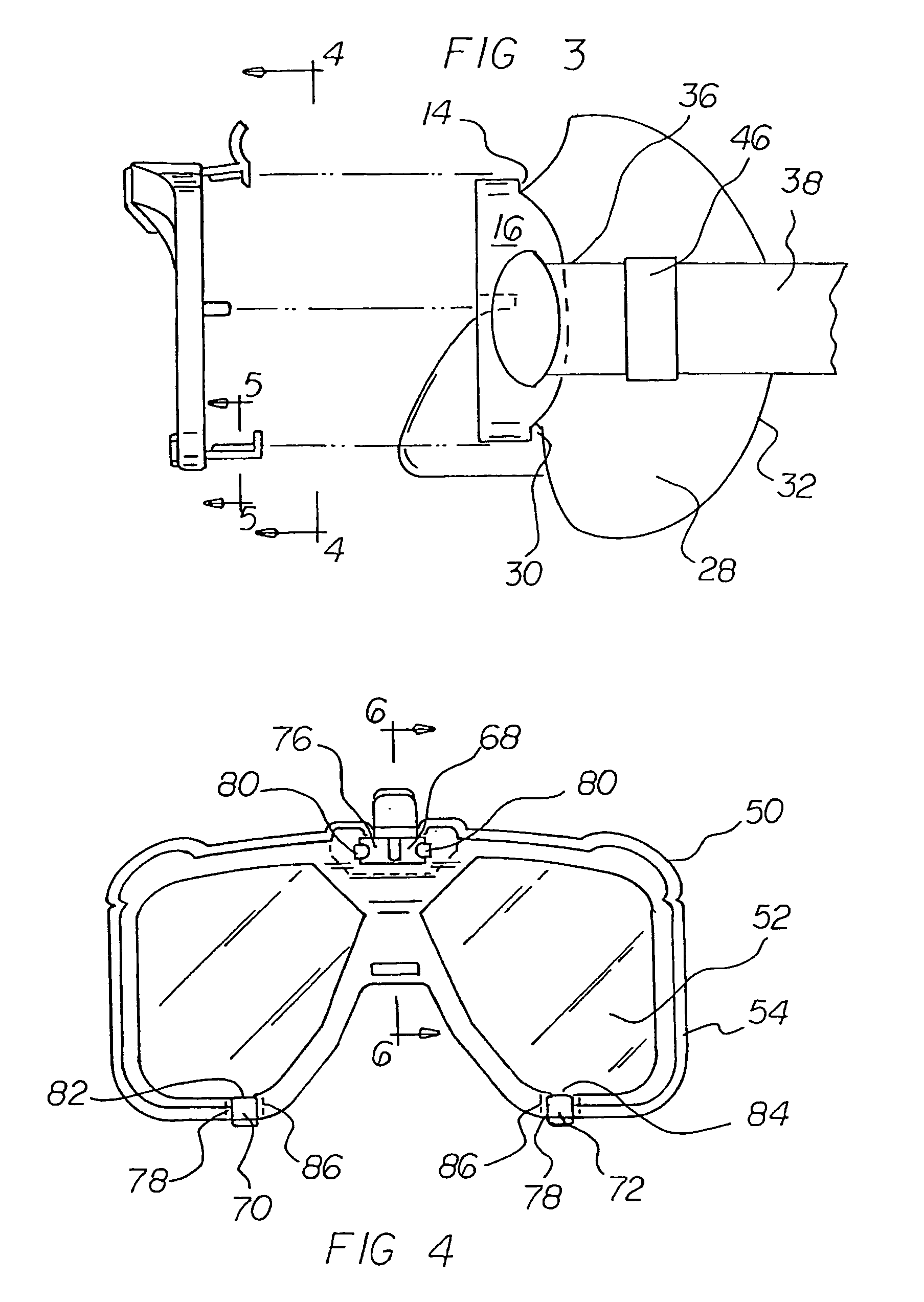
[0032]With reference now to the drawings, and in particular to FIG. 1 thereof, the preferred embodiment of the new and improved dive mask with optical filter system embodying the principles and concepts of the present invention and generally designated by the reference numeral 10 will be described.

[0033]The present invention, the dive mask with optical filter system 10 is comprised of a plurality of components. Such components in their broadest context include a mask assembly, a strap assembly, and a shield assembly. Such components are individually configured and correlated with respect to each other so as to attain the desired objective.

[0034]First provided is a mask assembly 14. The mask has two laterally spaced rigid circumferential frames 16, 18. Each frame has an interior edge 20 and an exterior edge 22. The exterior edge has an upper horizontal area, two lower horizontal areas and two laterally spaced vertical areas. The mask assembly also includes a clear primary lens 24, 26...


PUM


Abstract

A mask assembly has two circumferential frames with an interior edge, an exterior edge and a lens. The assembly includes a skirt with a forward edge coupled to the frames. The forward edge extends rearwardly and terminates at a periphery positionable on the face of a wearer. A strap assembly includes a strap that is positionable around the head of a wearer. Free ends are secured to the vertical areas. The free ends of the strap are for securement and adjustment. A shield assembly has a front area that is positionable in front of the frames and lenses. The assembly has a peripheral ledge. An upper projection that extends from the shield. A finger extends adjacent to the horizontal area of the frame. Projections extend from the shield. Each has a finger extending upwardly. The projections and fingers are adapted to releasably couple the shield assembly to the mask assembly.

Description

BACKGROUND OF THE INVENTION[0001]1. Field of the Invention[0002]The present invention relates to a dive mask with optical filter system and more particularly pertains to maximizing a diver's visibility as a function of the environment.[0003]2. Description of the Prior Art[0004]The use of diving equipment of known designs and configurations is known in the prior art. More specifically, diving equipment of known designs and configurations previously devised and utilized for the purpose of improving vision through water through known methods and apparatuses are known to consist basically of familiar, expected, and obvious structural configurations, notwithstanding the myriad of designs encompassed by the crowded prior art which has been developed for the fulfillment of countless objectives and requirements.[0005]By way of example, U.S. Pat. No. 5,033,818 issued Jul. 23, 1991 to Barr relates to an electronic diving system and face mask display. U.S. Pat. No. 5,363,151 issued Nov. 8, 199...

Claims


Application Information

Patent Timeline
Patent Type & Authority Patents(United States)
IPC IPC(8): G02C1/00B63C11/12
CPCB63C11/12G02C1/00B63C2011/022
Inventor DUFFY, CHARLES J.PAYNE, J. SCOTT
Owner ICARE INDS
Why Eureka
Try Eureka