Diesel particulate removing apparatus

a technology of particulate removal and removing apparatus, which is applied in the direction of data switching network, exhaust treatment electric control, separation process, etc., can solve the problems of increasing disadvantageously a pressure loss, increasing a pressure loss, and damage to the catalyst mounting filter, so as to increase the capture and remove the rate of particulates and low electric power

Inactive Publication Date: 2005-10-11
O DEN CORP TOKIO TOKYO
View PDF16 Cites 4 Cited by
  • Summary
  • Abstract
  • Description
  • Claims
  • Application Information

AI Technical Summary

Benefits of technology

[0013]In view of the above, it is an object of the present invention to provide a diesel particulates removing apparatus by which it is capable of increasing capturing and removing rate of the particulates, of activating catalyst with low electric power, and therefore it is capable of burning and removing the captured particulates to ensure that the filter can be reused.
[0017]a heat-resisting filter arranged in a subsequent stage of the metallic heat generation body in order to capture, burn, and eliminate the particulates in the diesel exhaust gas,
[0033]Also, a preferable mode is one wherein the catalyst mounting filter is a cylindrical filter having a catalyst mounted thereupon so as to accelerate burning of the captured particulates.
[0034]Also, a preferable mode is one wherein the catalyst mounting filter is a cylindrical filter including ceramics or alumina and having a catalyst mounted thereupon so as to accelerate burning of the captured particulates.
[0039]Also, a preferable mode is one wherein the hollow branched portion has a collision plate within the portion so as to assist speed reduction and dispersion of the diesel exhaust gas introduced from the inlet port.

Problems solved by technology

However, when the black fume removing filter of this kind has been used for a long time, the filter clogs easily with the particulates of collected black fume, thus increasing disadvantageously a pressure loss.
As a result, some particulates (fine particulates) may be left unburned, and the catalyst mounting filter 6 is clogged with the unburned particles, thus increasing a pressure loss.
In some cases, a large amount of unburned and collected particulates in the catalyst mounting filter 6 are ignited and cause damage to the catalyst mounting filter 6.
This causes breaking of a wire and degradation in durability of the ceramic heater 4.
Consequently, there is a problem that catalyst placed in downstream end portion of the catalyst mounting filter 6 is not activated sufficiently, and unburned particulates remain in that portion.

Method used


Image

  • Diesel particulate removing apparatus
  • Diesel particulate removing apparatus
  • Diesel particulate removing apparatus

Examples


embodiments

First Embodiment

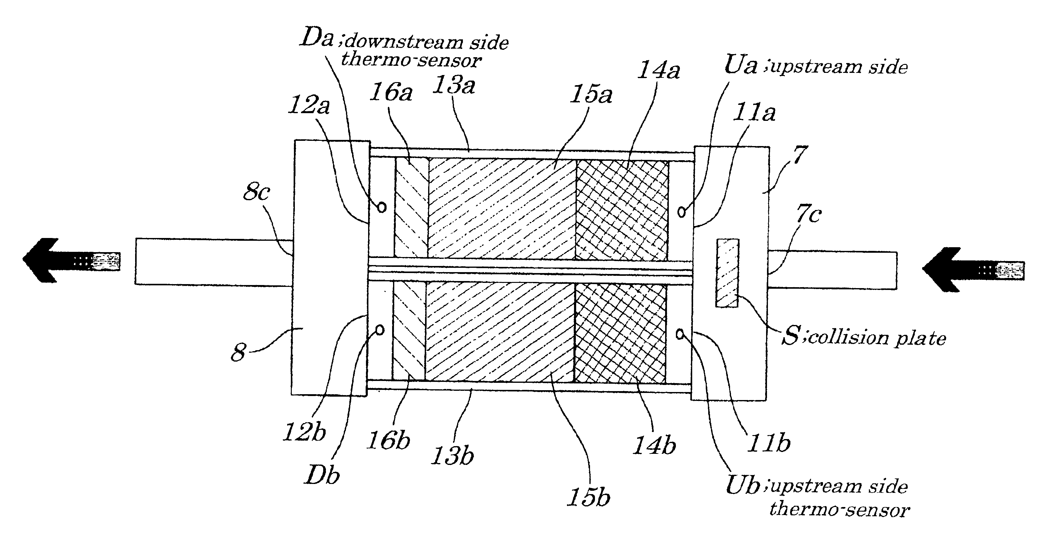
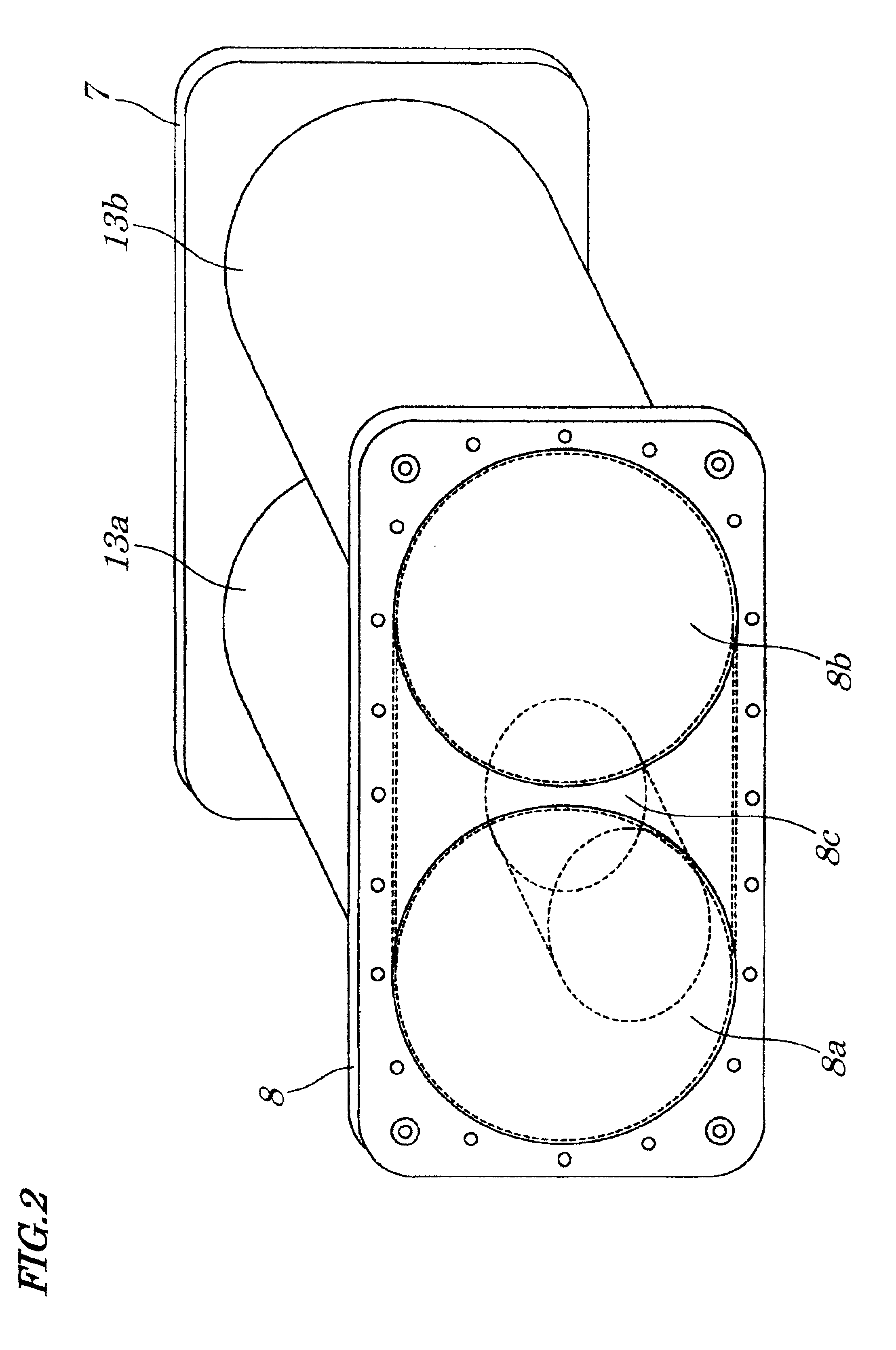
[0070]FIG. 1 is a sectional view showing an outline structure of a two-vessel type diesel particulate removing apparatus (hereinafter referred to as a two-vessel type apparatus) according to the first embodiment of the present invention; FIG. 2 is a front view of the two-vessel type apparatus; FIG. 3 is a diagrammatical front view of a catalyst mounting heater constituting the two-vessel type apparatus; FIG. 4 is an expanded view of a metallic heater constituting the catalyst mounting heater; FIG. 5 is a partly enlarged view of a catalyst mounting heater according to a modification; FIG. 6 is a partly enlarged view of a catalyst mounting heater according to another modification; FIG. 7 is a catalyst mounting heater according to still another modification; FIG. 8 is an explanatory view of an operation of the embodiment; and FIG. 9 is a flowchart showing operation processing steps of the embodiment.

[0071]The two-vessel type apparatus is mounted and used in a diesel veh...

second embodiment

[0096]FIG. 10 is a sectional view showing an outline structure of a two-vessel type apparatus according to a second embodiment of the present invention. Structures of the two-vessel type apparatus of the second embodiment which are vastly different from that of the first embodiment, are described below. Metal fiber-made filters 18a, 18b are placed at the back of catalyst cylindrical filters 16a, 16b making an apparatus of a four-stage catching structure. Making the apparatus of such four-stage structure is able to expect a fine particulate removing ratio to be raised or improved extraordinarily.

third embodiment

[0097]FIG. 11 is a sectional view showing an outline structure of a three-vessel type diesel particulate removing apparatus (hereinafter referred to as a three-vessel type apparatus) according to a third embodiment of the present invention; FIG. 12 is a front view of the three-vessel type apparatus; FIG. 13 is a perspective view of the three-vessel type apparatus, and FIG. 14 is a flowchart explaining operations of the third embodiment.

[0098]Structural difference of third embodiment from the second embodiment is that one vessel, an apparatus main body 9c, is added to apparatus main bodies 9a, 9b making a three-vessel structure.

[0099]When a diesel vehicle provided with the three-vessel structure above is subjected to a cold start, a control portion turns for example a catalyst mounting heater 14a placed within the apparatus main body 9a, to an ON state. Other catalyst mounting heaters 14a, 14c within the apparatus main bodies 9a, 9c are kept at their OFF state (step P1 of FIG. 14). T...


PUM

PropertyMeasurementUnit
temperatureaaaaaaaaaa
temperature differenceaaaaaaaaaa
temperatureaaaaaaaaaa

Abstract

A diesel particulate removing apparatus of a two-vessel three-layer catching structure has two main bodies. Respective main bodies have cylindrical vessels provided with inlet ports and outlet ports for a diesel exhaust gas. In the cylindrical vessel, rolled catalyst mounting heaters, heat-resisting filters, and catalyst mounting spherical filters are arranged in the order above at an inlet port of a diesel exhaust gas. These catalyst mounting heaters are alternatively turned ON or OFF.

Description

BACKGROUND OF THE INVENTION[0001]1. Field of the Invention[0002]The present invention relates to a diesel particulate removing apparatus and more particularly to a diesel particulate removing apparatus capturing particulates contained in an exhaust gas from an internal combustion engine such as a diesel engine by means of heaters and filters, burning the captured particulates, and removing the particulates from the filters to reuse or refresh the filters.[0003]The present application claims priorities of Japanese Patent Applications Nos.2000-355793 filed on Nov. 22, 2000 and 2000-366412 filed on Nov. 30, 2000 which are hereby incorporated by reference.[0004]2. Description of the Related Art[0005]Nowadays, the object of restriction to an automobile exhaust gas is nitrogen oxides (NOx), containing mainly carbon and nitrogen, which is said to be a cancer generating substance.[0006]Exhaust gas from diesel vehicles contains a number of carbon particulates (so called black fume or smoke)....

Claims


Application Information

Patent Timeline
Patent Type & Authority Patents(United States)
IPC IPC(8): B01D53/94F01N3/20F01N3/023F01N3/027F01N9/00F01N3/28F01N3/022F01N3/035F01N7/00F01N7/02F01N7/04B01D46/42F01N3/02F01N13/02F01N13/04
CPCB01D53/9481F01N3/0222F01N3/027F01N3/035F01N3/2026F01N3/2821F01N9/002F01N13/017F01N13/0097F01N2240/20F01N2330/02F01N2330/06F01N2330/10F01N2330/12F01N2330/38F01N2330/40F01N2510/065Y02T10/26Y02T10/47Y10S55/30Y02T10/12Y02T10/40F01N3/02
Inventor ENDO, KIYOMU
Owner O DEN CORP TOKIO TOKYO
Why Eureka
Try Eureka