Magnetic resonance imaging apparatus

a magnetic resonance imaging and gantry technology, applied in the direction of instruments, magnetic measurements, measurement devices, etc., can solve the problems of large noise, deformation of the sealed vessel itself, and leakage of magnetic fields from the two ends of the main coil, so as to improve the silencing ability of the gantry

Inactive Publication Date: 2005-10-11
TOSHIBA MEDICAL SYST CORP
View PDF34 Cites 83 Cited by
  • Summary
  • Abstract
  • Description
  • Claims
  • Application Information

AI Technical Summary

Benefits of technology

[0020]It is an object of the present invention to improve the silencing ability of the gantry of a magnetic resonance imaging apparatus.

Problems solved by technology

For this reason, the gradient coil spool considerably deforms at the leading and trailing edges of the gradient magnetic field, accompanying large noise.
However, it is inevitable that magnetic fields leak from the two ends of the main coil at which the shield coil ends.
The sealed vessel itself then deforms because of this eddy current, which in turn causes noise.
According to these conventional sound insulating methods, although the air-born propagation of noise can be prevented by a vacuum state, the solid-born propagation of noise due to contact for fixing operation cannot be prevented.
That is, these methods have not provided satisfactory measures against noise.
This makes it difficult to adjust the position of the gradient coil, and a long period of time is required for installation / adjustment, resulting in a high cost.
In addition, the means for supporting the gradient coil and the means for forming a sealed space around the gradient coil have complicated arrangements and require large numbers of parts.
As a consequence, the overall apparatus has a complicated arrangement and the cost increases.
At present, however, the noise reducing effects in these conventional magnetic resonance imaging apparatuses are concerned with only measures against noise originating from a gradient coil, and almost no measures are taken against noise caused by other portions, e.g., the vibrations of a cable connecting the gradient coil to an external power supply.
This sound makes the object feel unpleasant like noise from the gradient coil.
However, secondary problems have arisen owing to these silencing measures.
That is, an energy loss that cannot be neglected tends to occur in the resonance frequency band.
For the WB coil (resonating at the resonance frequency in terms of a circuit), the electric loss caused by that gradient coil becomes a load that cannot be neglected, resulting in a deterioration in the generation efficiency of an excitation RF magnetic field or reception sensitivity.
However, the loss caused by the mutual interference between the WB coil and the gradient coil without any shield is higher than the loss caused by the WB coil with the shield.
The gradient coil mechanically vibrates due to an electromagnetic force acting when the coil is driven, and hence becomes a sound (noise) source.
No suitable, specific proposal has not been made with regard to a case wherein the above shield is placed in such a silent type MRI apparatus.
As described above, this may increase the loss caused by the WB coil and cause a serious deterioration in function.
Furthermore, if the gradient coil is housed in the vacuum vessel in the above manner, since the discharge starting voltage in the vacuum vessel decreases, electric discharge tends to occur.
At present, however, no measures have been taken against such electric discharge.

Method used


Image

  • Magnetic resonance imaging apparatus
  • Magnetic resonance imaging apparatus
  • Magnetic resonance imaging apparatus

Examples


embodiment 1

(Embodiment 1)

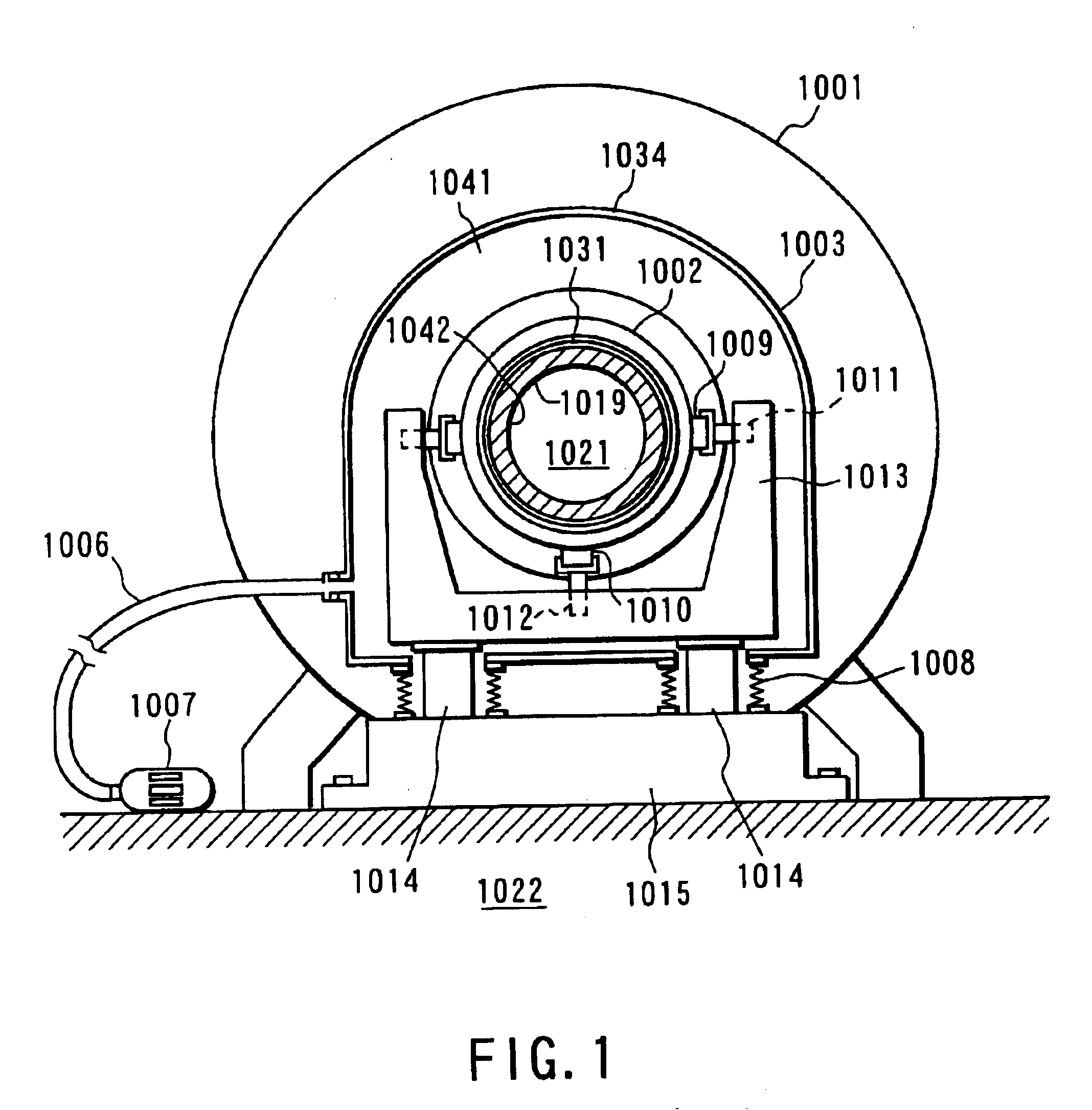
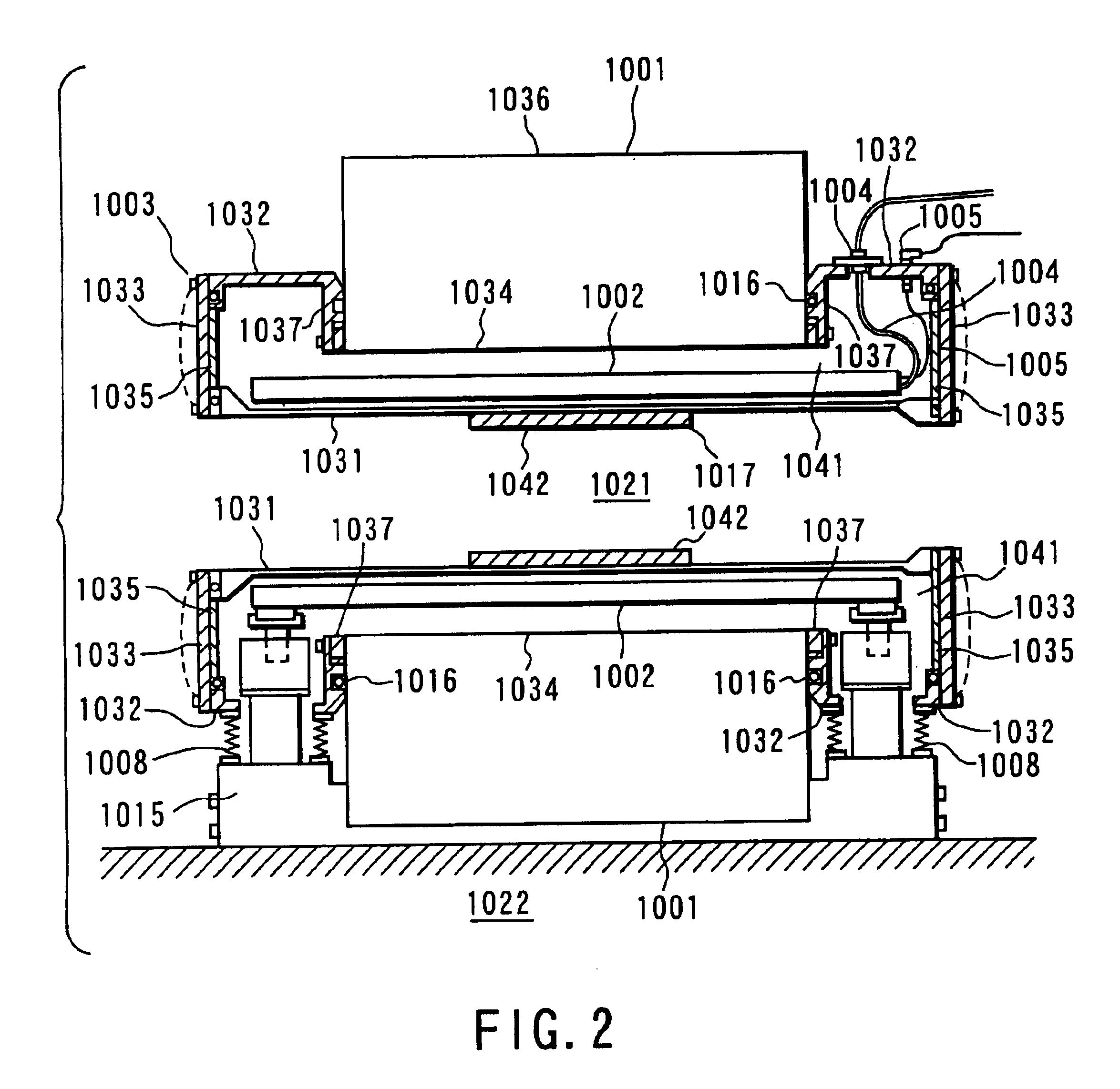
[0095]FIGS. 1 and 2 are respectively a cross-sectional view and longitudinal sectional view of the gantry of a magnetic resonance imaging apparatus according to Embodiment 1. The gantry includes a static magnetic field magnetic unit 1001, gradient coil unit 1041, and RF coil unit 1042. An imaging area 1022 having a substantially cylindrical shape is formed in substantially the central portion of the gantry. The gantry is fixed on a floor 1021 through a base 1015.

[0096]The static magnetic field magnetic unit 1001 generates a static magnetic field in the imaging area 1022, and is comprised of, if it is of a superconductive type, a superconductive coil, a liquid helium vessel housing the superconductive coil, and a sealed vessel 1036 housing the liquid helium vessel. The RF coil unit 1042 has an RF coil spool 1017 on which an RF coil pattern is formed. The RF coil spool 1017 is held by a cylindrical fiber-reinforced plastic liner 1031.

[0097]The gradient coil unit 1041 has...

embodiment 2

(Embodiment 2)

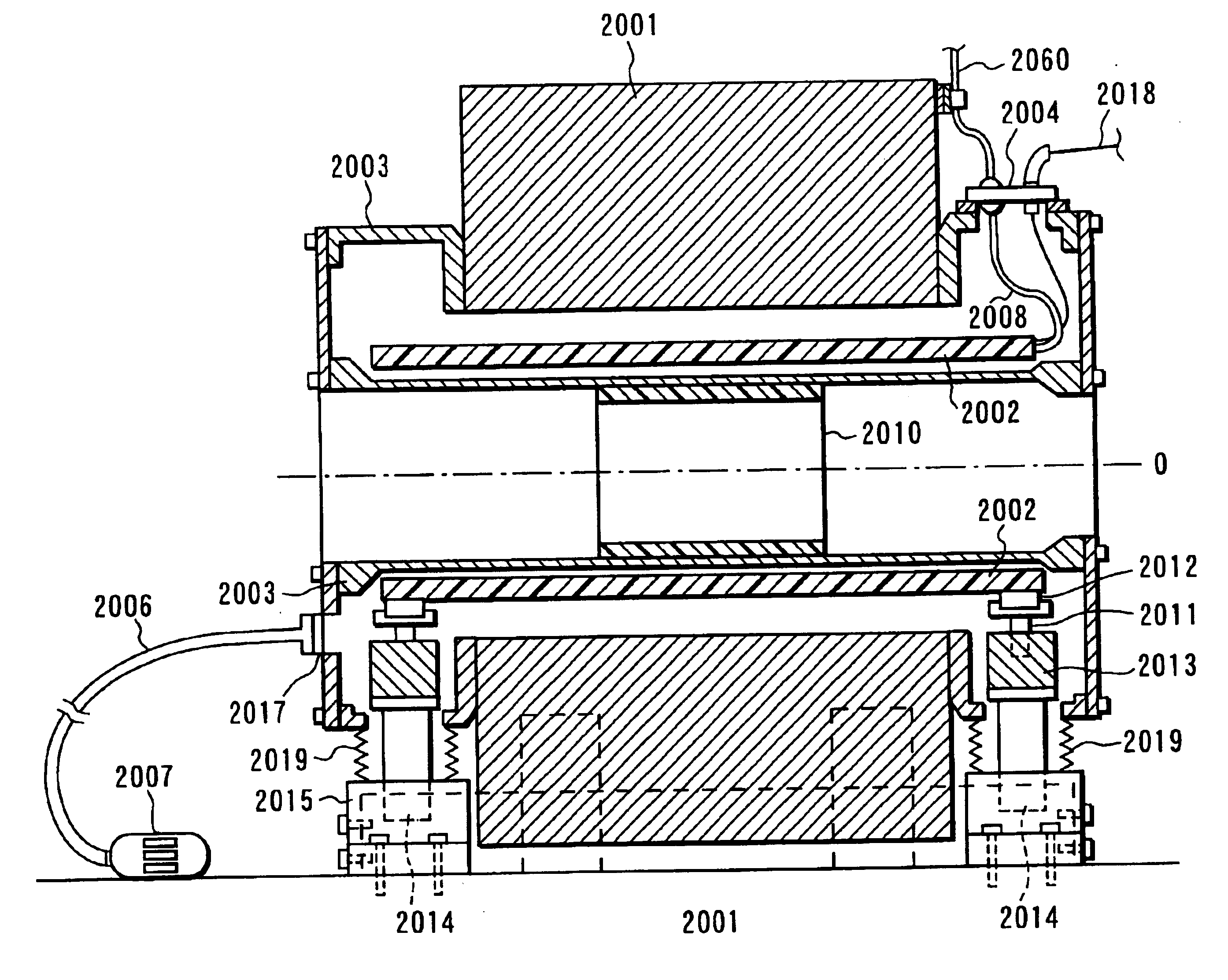
[0103]FIG. 3 is a longitudinal sectional view of the gantry of a magnetic resonance imaging apparatus according to Embodiment 2. A superconductive coil is housed in a cryostat 2001. This superconductive coil serves to give an imaging area a homogeneous static magnetic field. The static magnetic field strength required for general MR imaging operation is about 0.1 to 1 tesla. A static magnetic field is required to have a spatial homogeneity of several 10 ppm or less, and the imaging area has a spherical shape with a diameter of about 50 cm.

[0104]A gradient coil 2002 is placed in a sealed vessel 1003. The gradient coil 2002 serves to give a main magnetic field a linear gradient to determine an arbitrary imaging slice or add positional information to an RF signal from an object to be examined. In general, the gradient coil 2002 is constituted by three independent coil sets Gx, Gy, and Gz for generating gradient magnetic fields in orthogonal x-, y-, and z-axes. For example...

embodiment 3

(Embodiment 3)

[0119]FIG. 7A is a cross-sectional view of the gantry of a magnetic resonance imaging apparatus according to Embodiment 3. FIG. 7B is a longitudinal sectional view of the gantry. A gantry 3019 has an imaging space S having a substantially cylindrical shape, in which a patient is to be inserted / placed. An object 3008 to be examined is placed on a top 3009 and inserted into the imaging space S of the gantry 3019. The operations of the gantry 3019 and top 3009 are controlled by a control processing section. Assume that the axial direction of the imaging space S is the Z direction, and directions perpendicular to the Z direction are the X and Y directions. The gantry 3019 has a static magnetic field magnet formed by, for example, a superconductive magnet, which generates a static magnetic field in the imaging space S, and a cryostat 3001 housing the magnet. The cryostat 3001 is mounted on four leg members 3027 extending upright from a floor F. The floor F is made of, for e...


PUM


Abstract

The gantry of a magnetic resonance imaging apparatus includes a static magnetic field magnet, a gradient coil, a high-frequency coil, and a sealed vessel housing the gradient coil. The sealed vessel is made of a nonconductive material. Even if a gradient magnetic field is switched at high speed, no eddy current flows in the sealed vessel. Therefore, the sealed vessel does not vibrate.

Description

BACKGROUND OF THE INVENTION[0001]The present invention relates to a magnetic resonance imaging apparatus for generating a magnetic resonance signal (MR signal) by applying a gradient magnetic field pulse and high-frequency magnetic field pulse to an object to be examined which is placed in a homogeneous static magnetic field, and generating a magnetic resonance image (MR image) on the basis of this MR signal.[0002]As is known well, the magnetic resonance phenomenon is a phenomenon in which when nuclei having unique magnetic moments are placed in a homogeneous static magnetic field, they resonantly absorb the energy of high-frequency magnetic fields that rotate at specific frequencies. A magnetic resonance diagnosis apparatus is designed to visualize the chemical, structural, microscopic information of a substance in a living body by using this magnetic resonance phenomenon.[0003]Various types of visualizing techniques are available. The two-dimensional Fourier transform method (2DFT...

Claims


Application Information

Patent Timeline
Patent Type & Authority Patents(United States)
IPC IPC(8): G01V3/00G01R33/385
CPCG01R33/3854G01R33/3856
Inventor TAKAMORI, HIROMITSUIINUMA, KAZUHIROUOSAKI, YASUHIRO
Owner TOSHIBA MEDICAL SYST CORP
Why Eureka
Try Eureka