Method and apparatus for physical layer radar pulse detection and estimation

a physical layer and radar pulse technology, applied in the field of data communication, can solve the problems of insufficient present proposed radar detection methods and avoidance, and achieve the effect of convenient programming implementation

Inactive Publication Date: 2005-10-11
QUALCOMM INC
View PDF16 Cites 47 Cited by
  • Summary
  • Abstract
  • Description
  • Claims
  • Application Information

AI Technical Summary

Problems solved by technology

However, the present proposed methods of radar detection and avoidance are generally insufficient, especially in view of increased network traffic in the 5 GHz radio spectrum and the need for increased bandwidth among WLAN devices.

Method used


Image

  • Method and apparatus for physical layer radar pulse detection and estimation
  • Method and apparatus for physical layer radar pulse detection and estimation
  • Method and apparatus for physical layer radar pulse detection and estimation

Examples


Embodiment Construction

[0030]A radar detection system illustrative of the present invention is now described. For purposes of explanation, numerous specific details are set forth in order to provide a thorough understanding of the present invention. It will be evident, however, to one of ordinary skill in the art, that the present invention may be practiced without these specific details.

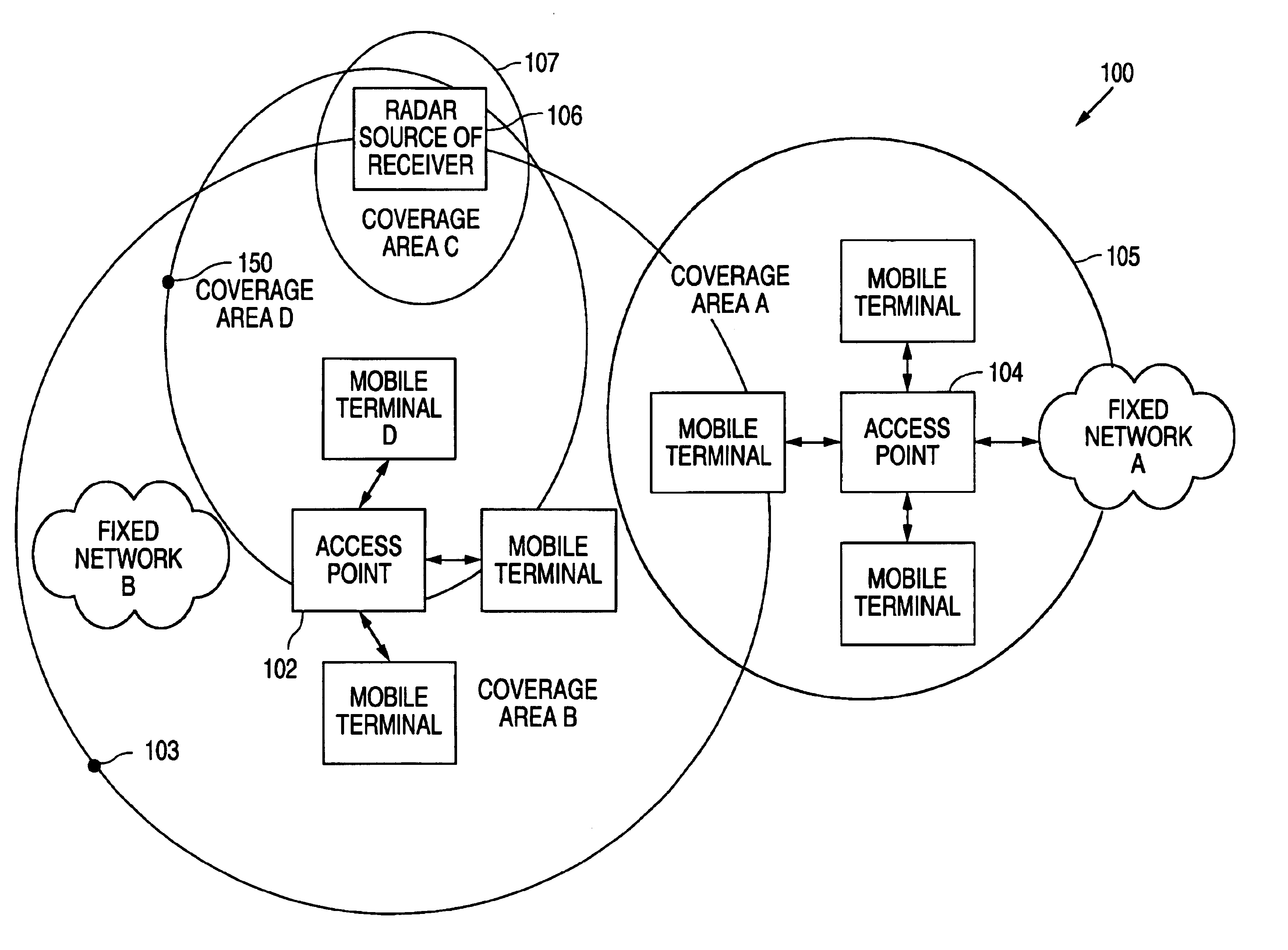
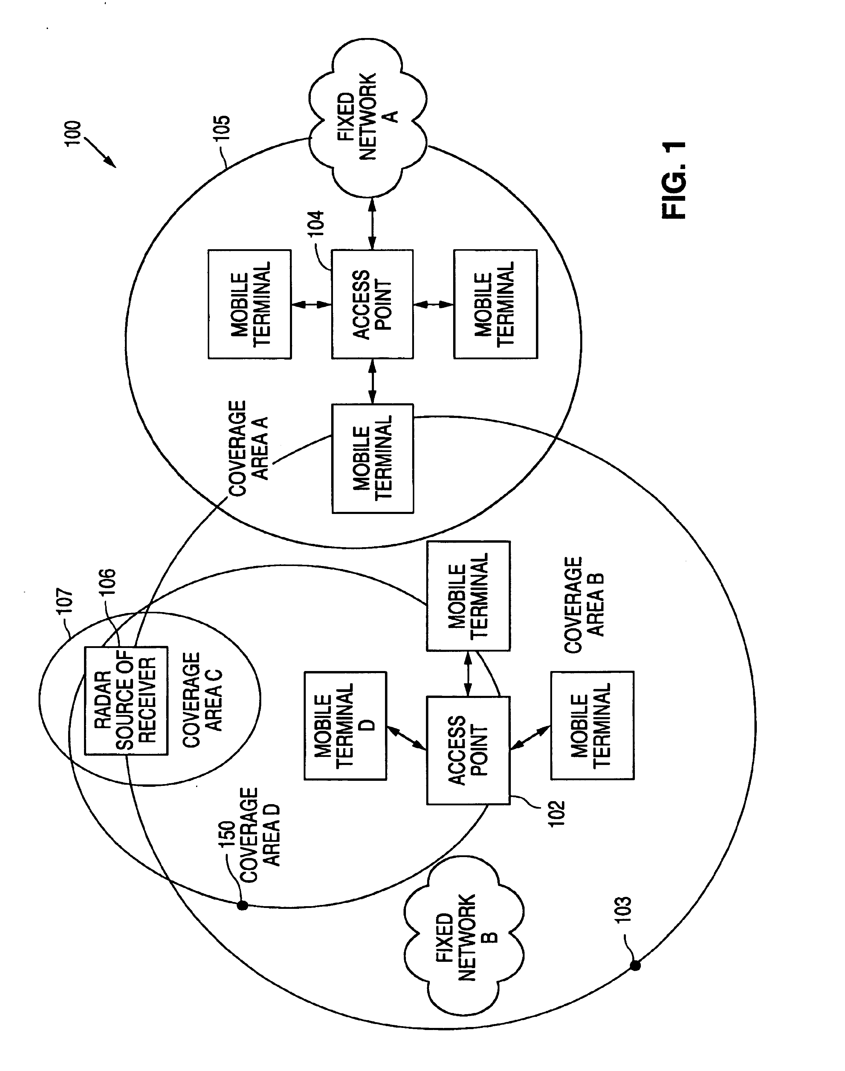
[0031]Various aspects of the present invention may be implemented within the hardware circuitry and / or software processes of a WLAN or Radio LAN (RLAN) device operating in the 5 GHz space. For purposes of the following discussion, the terms “Wireless LAN” and “Radio LAN” are used interchangeably to refer to a network for a device or devices that transmit in the 5 GHz space (e.g., IEEE 802.11a). Such a device could be an Access Point (AP), mobile terminal (node), or some other station within a greater wireless network. The wireless network device is configured to receive network traffic from other WLAN devices. However, th...


PUM


Abstract

Radar Pulse detection and radar signal length detection are used to detect and provide information for identifying radar signals. Pulse detection estimates a radar pulse size when it is too short for meaningful measurement. Pulse detection identifies a radar by identification of an in-band pulse without a communication or data packet encoded therein, or a communication error is detected with the in-band pulse. Signal length detection counts the length of a received signal after the received signal exceeds a radar threshold. The count identifies the received signal length upon drop of the power. The signal is identified as a radar when the power drops before a PHY error occurs, or when the power drop occurs after a PHY error and a delay time equivalent to the shortest radar signal. A radar signal is also identified upon a timeout wait for a power drop after a PHY error.

Description

RELATED APPLICATIONS[0001]This application is a divisional of U.S. application Ser. No. 10 / 138,953, filed May 3, 2002.COPYRIGHT NOTICE[0002]A portion of the disclosure of this patent document contains material which is subject of copyright protection. The copyright owner has no objection to the facsimile reproduction by anyone of the patent document or the patent disclosure, as it appears in the Patent and Trademark Office patent file or records, but otherwise reserves all copyright rights whatsoever.CROSS REFERENCE TO RELATED APPLICATIONS[0003]This invention claims is related to the following co-pending U.S. patent applications, which are incorporated herein by reference, in their entirety:[0004]McFarland et al., application Ser. No. 09 / 963,217, entitled “METHOD AND SYSTEM FOR DETECTING FALSE PACKETS IN WIRELESS COMMUNICATIONS SYSTEMS,”, filed, Sep. 25, 2001;[0005]U.S. patent application assigned to Atheros Communications entitled “RADAR DETECTION AND DYNAMIC FREQUENCY SELECTION FO...

Claims


Application Information

Patent Timeline
Patent Type & Authority Patents(United States)
IPC IPC(8): G01S7/02H04L12/56H04L12/28H04Q7/36H04W16/14H04W24/00H04W28/04
CPCG01S7/021H04W16/14H04K3/822H04W24/00H04K3/226H04K2203/18H04W28/04G01S13/66
Inventor HUSTED, PAULMCFARLAND, WILLIAM J.ZHANG, XIAORUTHOMPSON, JOHN
Owner QUALCOMM INC
Why Eureka
Try Eureka