Liquid crystal display panel and method for manufacturing the same

a liquid crystal display and liquid crystal technology, applied in non-linear optics, instruments, optics, etc., can solve the problems of inability to adequately satisfy the present demands of display applications, power consumption, and easy incorporation of impurities, and achieve the effects of low cost, easy hardening, and reliable formation

Inactive Publication Date: 2005-10-11
LG DISPLAY CO LTD
View PDF26 Cites 7 Cited by
  • Summary
  • Abstract
  • Description
  • Claims
  • Application Information

AI Technical Summary

Benefits of technology

[0025]In the LCD panel of the present invention, since a sealant provided within the panel can easily be hardened by transmitting UV-rays through an second substrate of the panel in areas absent a light-shielding material, UV-type hardening sealant may be used. The present invention is therefore useful for forming reliable, low cost, and / or high yield LCD panels, particularly large sized LCD panels.

Problems solved by technology

However, the CRT cannot adequately satisfy present demands for display applications that require reduced volume and weight, portability, and low power consumption while having a large screen size and high resolution.
Since liquid crystal has low specific resistance and easily absorbs moisture in the air, it is susceptible to incorporating impurities.
However, with currently developed liquid crystal materials, inorganic sealant generally is no longer used.
Moreover, when a thermal hardening resin is applied to large sized substrates, thermal expansion of the resins often occurs.
Heating the substrates at high temperatures may cause an increase in substrate stress due to thermal expansion of the sealant.
Another drawback is the long hardening time typically required for thermal hardening type sealant.
However, since an upper portion of the sealing region S is covered with the light-shielding layer, the transmission of UV-rays are substantially prevented from directly irradiating the sealant, thus making it difficult or impractical to use UV hardening type sealant.

Method used


Image

  • Liquid crystal display panel and method for manufacturing the same
  • Liquid crystal display panel and method for manufacturing the same
  • Liquid crystal display panel and method for manufacturing the same

Examples


Embodiment Construction

[0042]Reference will now be made in detail to the preferred embodiments of the present invention, examples of which are illustrated in the accompanying drawings.

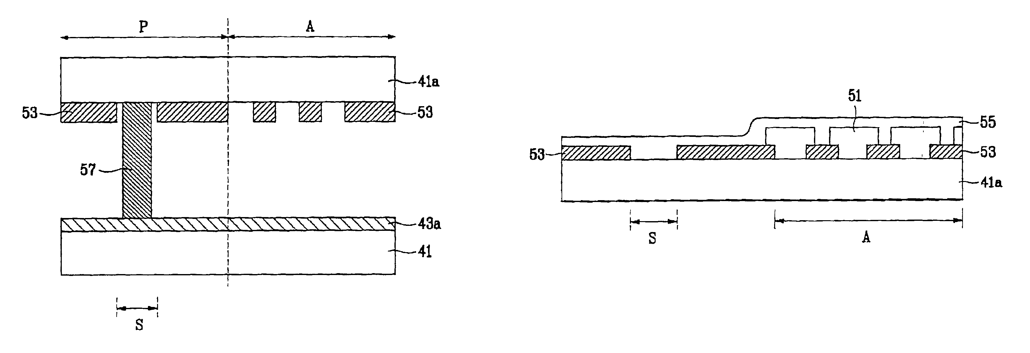
[0043]FIG. 4 is a plan view of an exemplary LCD panel embodiment of the present invention. As shown in FIG. 4, the LCD panel according to the present invention includes an active region A within the perimeter defined by dotted line 58 and a pad region P in areas outside the perimeter. The active region A may be provided with a plurality of TFTs that switch data signals representing an image onto pixel electrodes 49 displaying the image.

[0044]As shown in FIG. 5, a sealant 57 is provided in a sealing region S defined outside and along a periphery of the active region A. A light-shielding layer 53 may be formed in the active region A and in the pad region P, but light-shielding layer 53 is not formed the sealing region S. The sealant 57 may be formed between a first substrate 41 and a second substrate 41a as two or more separat...


PUM

PropertyMeasurementUnit
brightnessaaaaaaaaaa
volumeaaaaaaaaaa
weightaaaaaaaaaa

Abstract

An LCD panel and a method for manufacturing the same facilitate more efficient hardening a UV-type hardening sealant suitable for a large size panel. The LCD panel includes first and second substrates, an active region defined on the first substrate and provided with a plurality of TFT's and pixel electrodes, a sealing region defined along a periphery of the active region, a light-shielding region defined on the second substrate other than on the sealing region, and a liquid crystal region between the first and second substrates. The method for manufacturing an LCD panel includes the steps of preparing first and second substrates, forming a plurality of patterns in an active region on the first substrate, forming a UV hardening type sealant along a periphery of the active region, forming a light-shielding layer on the second substrate so as not to shield the sealant, attaching the first and second substrates to each other, and irradiating the sealant with UV-rays to harden the sealant.

Description

[0001]This application claims the benefit of Korean Patent Application No. P 2000-62983, filed on Oct. 25, 2000, which is hereby incorporated by reference.BACKGROUND OF THE INVENTION[0002]1. Field of the Invention[0003]The present invention relates to a display device, and more particularly, to a liquid crystal display (LCD) panel and a method for manufacturing the same.[0004]2. Discussion of the Related Art[0005]Rapid development within the fields of information and communication has caused an increase in the demand for thin, lightweight and low cost display devices for viewing information. Industries that develop displays are responding to these needs by placing high emphasis on developing flat panel type displays.[0006]Historically, the Cathode Ray Tube (CRT) has been widely used as a display device in applications such as televisions, computer monitors, and the like, because CRT screens can display various colors having high brightness. However, the CRT cannot adequately satisfy...

Claims


Application Information

Patent Timeline
Patent Type & Authority Patents(United States)
IPC IPC(8): G02F1/1335G02F1/1339G02F1/136
CPCG02F1/133512G02F1/1339G02F1/136
Inventor YOUN, WON GYUNKIM, KYEONG JIN
Owner LG DISPLAY CO LTD
Why Eureka
Try Eureka