Production method for making position-sensitive radiation detector arrays

a radiation detector and production method technology, applied in the field of positron emission tomography (pet), can solve the problems of reducing detection sensitivities, small crystal elements, and large loss of coincidence detection efficiency of very small detectors, and achieves a much simplified production process, improved detection efficiency, and improved detection efficiency.

Inactive Publication Date: 2005-10-18
BOARD OF RGT THE UNIV OF TEXAS SYST
View PDF28 Cites 28 Cited by
  • Summary
  • Abstract
  • Description
  • Claims
  • Application Information

AI Technical Summary

Problems solved by technology

This process is satisfactory for the larger crystal elements used in lower resolution cameras but not for the very high resolution, small crystal elements, cameras.
One reason is the substantial loss in coincidence detection efficiency for very small detectors due to the width of the grooves created by the saw blade, as
However, the gaps between the crystals also reduce detection sensitivities.
Furthermore, since individual crystals have to be cut and polished mechanically or chemically, this process is more labor intensive.
A problem with manufacturing individual crystals for the detectors is in the actual placement of the individual crystals into the array.
The buildup of tens of thousands of small mechanical errors (i.e., 0.1 mm per detector) can be a significant error relative to the small sizes of the crystals, which can place some crystals in the detector arrays too far from its expected position, which can degrade the imaging accuracy.
Another disadvantage of conventional approaches has been the high cost of manufacturing each crystal individually.
A problem with cutting uneven grooves into the scintillation material has been that the depth of the cut in the crystal is very deep at the ends of the block, and the small amount of material left to connect the channels is easily breakable.
If the material breaks, the whole detector crystal block is wasted and unusable.
This additional process may be time and cost extensive, as it may require the grinding of each individual crystal.
For scintillation crystals blocks created by cutting groves into the blocks, additional grinding may increase the odds of creating a defective crystal block by breaking off crystals at the ends of the blocks.
Heretofore, the requirements of a more durable scintillation detector array, decreased mechanical errors in the arrays, decreased gaps between crystals, and decreased cost of capital and time in the manufacturing of the detector arrays have not been fully met.

Method used


Image

  • Production method for making position-sensitive radiation detector arrays
  • Production method for making position-sensitive radiation detector arrays
  • Production method for making position-sensitive radiation detector arrays

Examples


example 1

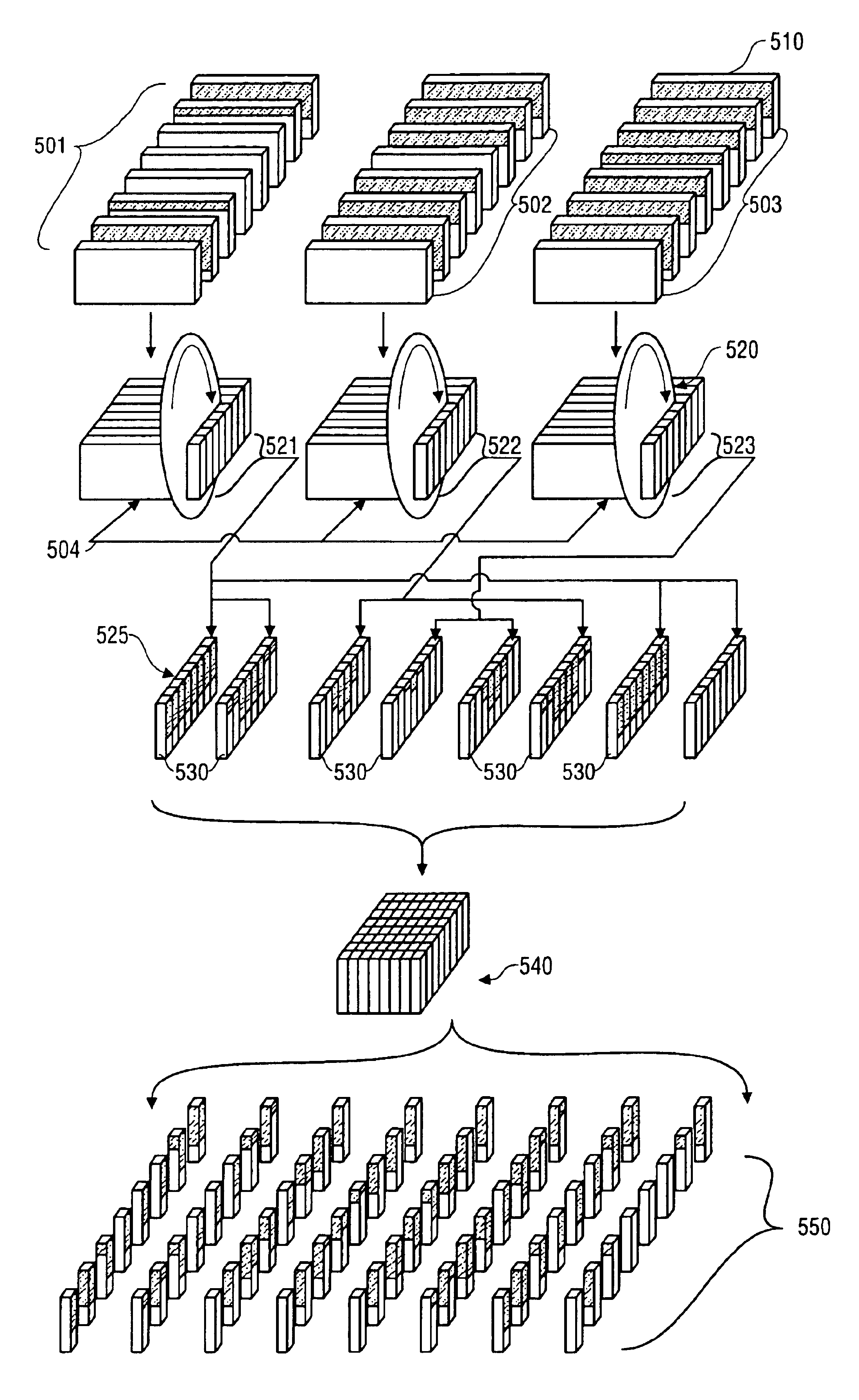
[0135]Table 1a and Table 1b show an example of the mask configuration of a 7×7 embodiment of a detector array made by the process of the invention. The information in Tables 1a and 1b are also illustrated in FIG. 28. Scintillation crystal slabs 2100, of a length longer than the intended detector array length, are painted with a number of linear masks 2110 of varying lengths. The crystal slabs are then glued together using an optical glue to form sandwich structures 2106, 2107.

[0136]The sandwiches 2106, 2107 are then cut into slices 2120. Slices from each sandwich type 2106, 2107 are chosen 2121, 2122 and a second set of masks 2130 are painted on the slices 2121, 2122. These slices 2121, 2122 are then glued together to form the final detector array 2150. The resulting detector array 2150, which when broken down into its component pieces, is comprised of individual crystals 2155 that have a first mask 2110 and a second mask 2130 painted on each of two of its facets 2155. When the mask...

example 2

[0140]Table 2a and Table 2b show an example of the mask configuration of a 7×8 embodiment of a detector array made by the process of the invention. The information in Tables 2a and 2b are also illustrated in FIG. 29. Scintillation crystal slabs 2200, of a length longer than the intended detector array length, are painted with a number of linear masks 2210 of varying lengths. The crystal slabs are then glued together using an optical glue to form sandwich structures 2206, 2207, 2208, 2209.

[0141]The sandwiches 2206, 2207, 2208, 2209 are then cut into slices 2220. Slices from each sandwich type 2206, 2207, 2208, 2209 are chosen 2221, 2222, 2223, 2224 and a second set of masks 2230 are painted on the slices 2221, 2222, 2223, 2224. These slices 2221, 2222, 2223, 2224 are then glued together to form the final detector array 2250. The resulting detector array 2250, which when broken down into its component pieces, is comprised of individual crystals 2255 that have a first mask 2210 and a s...

example 3

[0145]Table 3a and Table 3b show an example of the mask configuration of a 8×8 embodiment of a detector array made by the process of the invention. The information in Tables 3a and 3b are also illustrated in FIG. 30. Scintillation crystal slabs 2300, of a length longer than the intended detector array length, are painted with a number of linear masks 2310 of varying lengths. The crystal slabs are then glued together using an optical glue to form sandwich structures 2306, 2307, 2308, 2309.

[0146]The sandwiches 2306, 2307, 2308, 2309 are then cut into slices 2320. Slices from each sandwich type 2306, 2307, 2308, 2309 are chosen 2321, 2322, 2323, 2324 and a second set of masks 2330 are painted on the slices 2321, 2322, 2323, 2324. These slices 2321, 2322, 2323, 2324 are then glued together to form the final detector array 2350. The resulting detector array 2350, which when broken down into its component pieces, is comprised of individual crystals 2355 that have a first mask 2310 and a s...


PUM


Abstract

Systems and methods are described for a production method for making position-sensitive radiation detector arrays. A method includes applying a plurality of masks to a plurality of scintillation crystal slabs; coupling the plurality of scintillation crystal slabs to form a sandwich structure; cutting a plurality of slices from the sandwich structure; and coupling at least two of the plurality of slices to form a detector array.

Description

CROSS-REFERENCE TO RELATED APPLICATION[0001]This application is related to and claims a benefit of priority to U.S. Ser. No. 60 / 353,136, filed on Feb. 1, 2002, the entire contents of which are hereby expressly incorporated by reference for all purposes.STATEMENT AS TO RIGHTS TO INVENTIONS MADE UNDER FEDERALLY-SPONSORED RESEARCH AND DEVELOPMENT[0002]This invention was made with United States Government support under contract to the National Institute of Health. The Government may have certain rights in this invention.BACKGROUND OF THE INVENTION[0003]1. Field of the Invention[0004]The invention relates generally to the field of Positron Emission Tomography (PET). More particularly, the invention relates to scintillation radiation detectors in PETs. Specifically, a preferred implementation of the invention relates to the manufacture of the scintillation radiation detectors.[0005]2. Discussion of the Related Art[0006]Positron emission tomography (PET) is a technique for measuring the co...

Claims


Application Information

Patent Timeline
Patent Type & Authority Patents(United States)
IPC IPC(8): G01T1/164G01T1/20G01T1/00G01TG01T1/161G01T1/202G01T1/29H01L27/14H01L31/09
CPCG01T1/2002A61B6/037G01T1/2985G01T1/202
Inventor WONG, WAI-HOIURIBE, JORGEBAGHAEI, HOSSAINLI, HONGDI
Owner BOARD OF RGT THE UNIV OF TEXAS SYST
Why Eureka
Try Eureka