

Switching power supply controller and switching power supply
- Summary
- Abstract
- Description
- Claims
- Application Information
AI Technical Summary
Benefits of technology
Problems solved by technology
Method used
Image

Examples
first embodiment
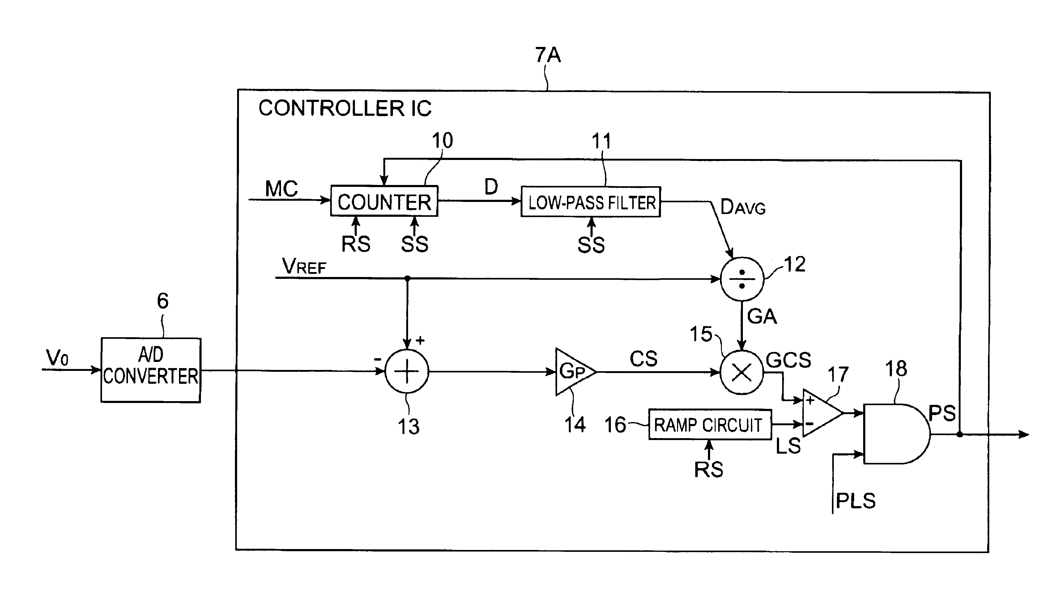
[0061]In the first embodiment, the counter 10 and the low-pass filter 11 correspond to the duty ratio generating means in the claims; the low-pass filter 11 to the duty ratio averaging means in the claims; the divider 12 to the gain adjustment value setting means in the claims; the subtractor 13 and the multiplier 14 to the control signal generating means in the claims; the multiplier 14 to the gain adjustment means in the claims; the multiplier 15 to the operation means in the claims; the ramp circuit 16 and the comparator 17 to the drive signal generating means in the claims.
[0062]The counter 10 detects the pulse width D (duty ratio) of the PWM signal PS. For that, the counter 10 receives the PWM signal PS generated in the controller IC 7A, and the reset signal RS and the sample clock signal SS. The counter 10 performs a count-up operation every cycle of the master clock MC during a period in which the PWM signal PS is high. The counter 10 holds a count-up value while the PWM sign...
second embodiment
[0089]In the second embodiment, the D flip-flop circuit 19 corresponds to the delay device in the claims.
[0090]The D flip-flop circuit 19 detects the duty ratio D. For that, the D flip-flop circuit 19 receives the gain adjustment control signal GCS generated in the controller IC 7B and receives the PWM signal PS as a clock signal. The D flip-flop circuit 19 holds a value of the gain adjustment control signal GCS at a fall of a pulse of the PWM signal PS (a switchover from the high level to the low level) and outputs the held value of the gain adjustment control signal GCS to the limiter circuit 20 until a fall of a pulse in a next cycle of the PWM signal PS (cf. FIGS. 8(a) to (c)). Since falls of pulses of the PWM signal PS (i.e., the pulse widths D) are defined at points where the value of the gain adjustment control signal GCS equals the value of the ramp signal LS, the value of the gain adjustment control signal GCS at a fall of each pulse of the PWM signal PS is equivalent to th...
third embodiment
[0097]In the third embodiment, the table 21 and the multiplier 22 correspond to the gain adjustment value setting means in the claims; the table 21 to the converting means in the claims.
[0098]The table 21 is a table in which table values TV are set as values for conversion of target voltage VREF. The table values TV set in the table 21 are not inverse values of the target voltage VREF (TV against VREF indicated by a dashed line in FIG. 10), but values of a first-order function having a negative proportionality factor (e.g., −1) with the target voltage VREF as a parameter (TV against VREF indicated by a solid line in FIG. 10). In passing, the table 21 is preliminarily stored in a memory means such as ROM or the like in the controller IC 7C.
[0099]The multiplier 22 receives a table value TV of the table 21 according to the target voltage VREF, and the average pulse width DAVG from the low-pass filter 11, multiplies the average DAVG by the table value TV, and outputs the product DAVG×TV...
PUM
 Abstract
Description
Claims
Application Information