Method and apparatus for imaging absorbing objects in a scattering medium

a scattering medium and object technology, applied in the field of imaging techniques, can solve the problem of not providing for identifying the absorbing pattern in this region

Inactive Publication Date: 2005-10-18
THE STATE OF ISRAEL ATOMIC ENERY COMMISSION SOREQ NUCLEAR RES CENT
View PDF5 Cites 59 Cited by
  • Summary
  • Abstract
  • Description
  • Claims
  • Application Information

AI Technical Summary

Benefits of technology

[0007]The present invention takes advantage of the acoustic tagging of the light technique enabling identification of the locations inside the medium corresponding to the detected scattered light components. In other words, irradiation of the medium with acoustic waves is used solely for the purpose of mapping the detected scattered light components. The acoustic tagging of light provides for obtaining the 3-D representation (map) of the medium in real-time. Although this representation by itself is indicative of the location of an absorbing region, it does not provide for identifying the absorbing pattern within this region (inter alia, because of the cross talk between the different paths that light tends to take within the patterned region).

Problems solved by technology

Although this representation by itself is indicative of the location of an absorbing region, it does not provide for identifying the absorbing pattern within this region (inter alia, because of the cross talk between the different paths that light tends to take within the patterned region).

Method used


Image

  • Method and apparatus for imaging absorbing objects in a scattering medium
  • Method and apparatus for imaging absorbing objects in a scattering medium
  • Method and apparatus for imaging absorbing objects in a scattering medium

Examples


Embodiment Construction

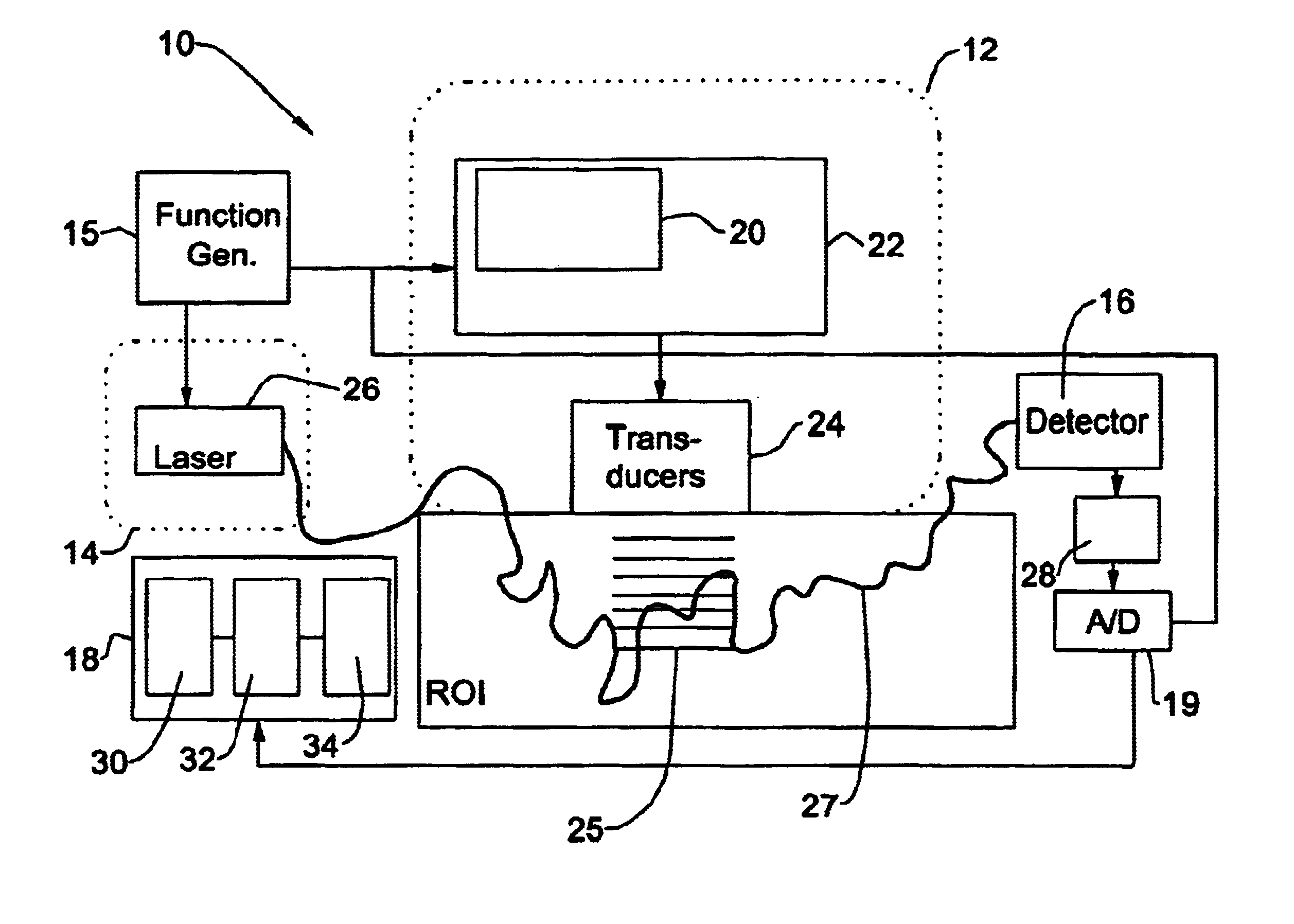
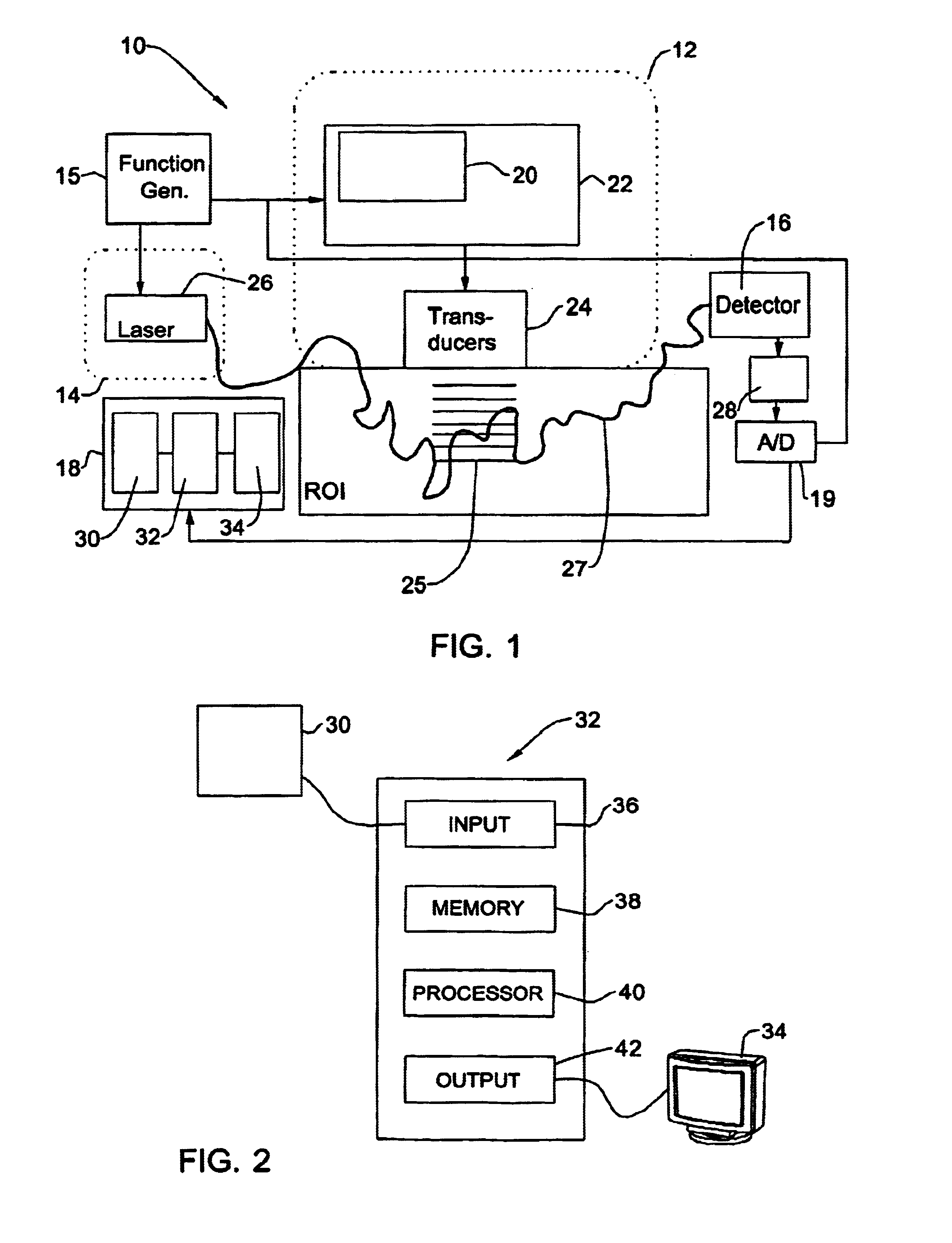
[0031]Referring to FIG. 1, there is illustrated a measurement apparatus 10 for obtaining a map of intensity of the distribution of light scattered from a plurality of known locations with a region of interest (ROI) in a scattering medium (for example, biological tissue) utilizing ultrasound tagging of light. The apparatus 10 comprises such main constructional parts as an ultrasound (generally, acoustic) unit 12 coupled to the medium, an illuminator 14 (constituting an electromagnetic radiation source) optically coupled to the medium, a detector 16, whose output is connectable to a control unit 18. The apparatus 10 also comprises a phase and frequency control utility 20, which, in the present example, is associated with the ultrasound unit 12, which comprises an acoustic or ultrasound generator 22 (possibly including an electronic beam forming unit and an array of amplifiers), and a transducer arrangement 24. The operation of the ultrasound unit 12 is aimed at delivering the proper u...


PUM

PropertyMeasurementUnit
wavelengthaaaaaaaaaa
wavelengthsaaaaaaaaaa
frequencyaaaaaaaaaa

Abstract

A method and processing device are presented for reconstructing an absorption and/or scattering image of a region of interest inside a scattering medium. A mathematical model is provided being representative of a relation between the distribution of the intensity and phase of electromagnetic radiation components scattered from a medium and a certain attenuation factor, which is function of spatial variations of scattering and absorption coefficients of the medium. The mathematical is used for processing a map of distribution of the intensity of electromagnetic radiation components scattered from known locations within the region of interest, thereby producing a halftone pattern of the region of interest.

Description

FIELD OF THE INVENTION[0001]This invention is generally in the field of imaging techniques, and relates to a method and apparatus for real-time imaging of absorbing objects within a scattering medium. The invention utilizes ultrasound tagging of light, and is particularly useful for non-invasive detection / measurements of absorbing agents, such as hemoglobin, in biological tissues.BACKGROUND OF THE INVENTION[0002]In recent years, much effort has been devoted to map the inside of diffusive bodies using ultrasound and electromagnetic waves. If a sound (or ultrasound) wave is located inside a scattering medium and concurrently a continuous electromagnetic wave (such as a laser light beam) crosses said medium and is strongly diffused thereby, the electromagnetic wave frequency is shifted by the sound frequency (acousto-optic effect) at the location of the sound (or ultrasound) wave, while in the other regions, the frequency of the light is unchanged. The electromagnetic waves with the sh...

Claims


Application Information

Patent Timeline
Patent Type & Authority Patents(United States)
IPC IPC(8): A61B5/00G01N21/47A61B8/00
CPCA61B5/0048A61B5/0059A61B5/0097G01N21/4795A61B8/00
Inventor SFEZ, BRUNO GADGRANOT, ERELLEV, ANERKOTLER, ZVI
Owner THE STATE OF ISRAEL ATOMIC ENERY COMMISSION SOREQ NUCLEAR RES CENT
Why Eureka
Try Eureka