
Method and apparatus for embedded built-in self-test (BIST) of electronic circuits and systems

a built-in self-testing and electronic circuit technology, applied in error detection/correction, measurement devices, instruments, etc., can solve the problems of adding to the total system cost and complexity, requiring typically not to be placed in the scan chain, and other support circuitry the microprocessor, so as to reduce the engineering effort for development and debugging of scan vectors, reduce the overhead of circuits, and reduce costs

Inactive Publication Date: 2005-10-18
INTELLITECH INC
View PDF20 Cites 49 Cited by
  • Summary
  • Abstract
  • Description
  • Claims
  • Application Information

AI Technical Summary

Benefits of technology

"The present invention provides an embedded electronic system that includes a built-in self-test (BIST) controller architecture. This architecture facilitates testing and debugging of electronic circuits and programmable devices. The BIST controller architecture reduces costs associated with circuit implementation and scan vector development, and also reduces the time required for custom software development and debugging. It includes a code-less solution that requires less circuitry to implement, thereby reducing both the cost and circuit area needed for the BIST solution. The BIST controller architecture can be embedded within a system to be tested, on one or more PCBs of the system to be tested, and / or on one or more ICs of the system to be tested, while reducing circuit overhead. It can be implemented either within an existing IC in the system or as a separate dedicated test circuit. Overall, the BIST controller architecture reduces costs and improves time-to-market."

Problems solved by technology

However, signal clashes may result when connecting the multiple TDO outputs onto the single TDO wire of the multi-drop bus.
This requires extra work in addition to test development and debug with the external test controller and therefore adds to the total system cost and complexity.
However, the microprocessor 402 and any other support circuitry the microprocessor 402 requires typically cannot be placed in the scan chain(s) of the system during embedded testing because this circuitry is employed to apply and analyze the embedded tests.
So, although this approach may reduce circuit costs for embedded BIST implementation, test costs may increase.
For example, the microprocessor infrastructure of the system may require a separate test methodology and development effort, and may be unable to take advantage of the structured scan methodologies of the remainder of the system.
The need for embedded BIST capabilities in PCBs and systems has grown considerably as the designs of ICs, PCBs, and systems have become more complex.

Method used


Image

  • Method and apparatus for embedded built-in self-test (BIST) of electronic circuits and systems
  • Method and apparatus for embedded built-in self-test (BIST) of electronic circuits and systems
  • Method and apparatus for embedded built-in self-test (BIST) of electronic circuits and systems

Examples


Embodiment Construction

[0036]U.S. Provisional Patent Application No. 60 / 336,586 filed Dec. 4, 2001 is incorporated herein by reference.

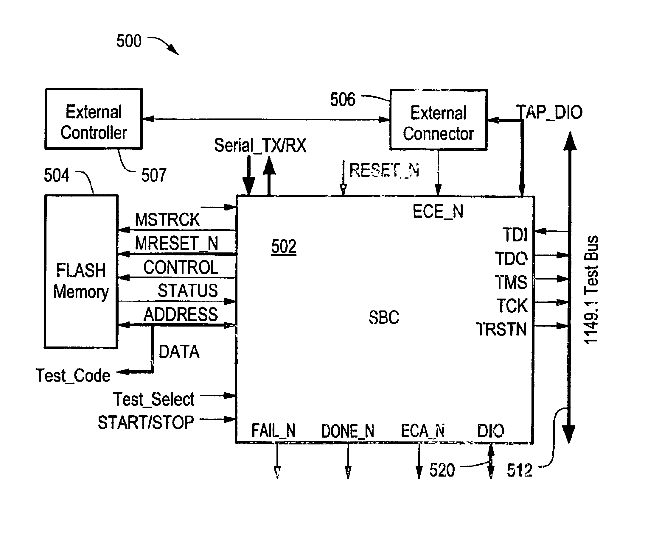
[0037]FIG. 5 depicts an illustrative embodiment of an electronic system Built-In Self-Test (BIST) controller architecture 500, in accordance with the present invention. In the illustrated embodiment, the system BIST controller architecture 500 includes an embedded IEEE 1149.1 bus 512, an embedded system BIST controller 502 coupled to the IEEE 1149.1 bus 512 and a Digital I / O (DIO) bus 520, an embedded memory 504 coupled to the system BIST controller 502, and an external connector 506 coupled to the system BIST controller 502. The external connector 506 is coupleable to an external test controller 507. In a preferred embodiment, the memory 504 comprises one or more FLASH memory devices such a FLASH EPROM or a FLASH EEPROM. It is understood, however, that the memory 504 may alternatively comprise any suitable type of non-volatile storage including a magnetic disk. Further, t...


PUM


Abstract

An embedded electronic system built-in self-test controller architecture that facilitates testing and debugging of electronic circuits and in-system configuration of programmable devices. The system BIST controller architecture includes an embedded system BIST controller, an embedded memory circuit, an embedded IEEE 1149.1 bus, and an external controller connector. The system BIST controller is coupled to the memory circuit and the IEEE 1149.1 bus, and coupleable to an external test controller via the external controller connector. The external test controller can communicate over the IEEE 1149.1 bus to program the memory and / or the system BIST controller circuitry, thereby enabling scan vectors to be debugged by the external test controller and then downloaded into the memory for subsequent application to a unit under test by the system BIST controller.

Description

CROSS REFERENCE TO RELATED APPLICATIONS[0001]This application claims priority of U.S. Provisional Patent Application No. 60 / 336,586 filed Dec. 4, 2001 entitled METHOD AND APPARATUS FOR EMBEDDED BUILT-IN SELF-TEST (BIST) OF ELECTRONIC CIRCUITS AND SYSTEMS.STATEMENT REGARDING FEDERALLY SPONSORED RESEARCH OR DEVELOPMENT[0002]N / ABACKGROUND OF THE INVENTION[0003]The present invention relates generally to Built-In Self-Test (BIST) of Integrated Circuits (ICs), Printed Circuit Boards (PCBs), and systems, and more specifically to an apparatus and method for embedding BIST capability within ICs, PCBs, and systems.[0004]Techniques are known that employ scan testing for providing manufacturing test, debug, and programming of electronic circuits. Such scan testing techniques are often performed according to the IEEE 1149.1 Standard Test Access Port and Boundary Scan Architecture specification (“the IEEE 1149.1 Standard”), which is incorporated herein by reference. The IEEE 1149.1 Standard may a...

Claims


Application Information

Patent Timeline
Patent Type & Authority Patents(United States)
IPC IPC(8): G01R31/3185G01R31/28
CPCG01R31/318544G01R31/318555
Inventor RICCHETTI, MICHAELCLARK, CHRISTOPHER J.
Owner INTELLITECH INC
Learn More