Flexible assembly of once-through evaporation for horizontal heat recovery steam generator

Active Publication Date: 2005-10-25
GENERAL ELECTRIC TECH GMBH
View PDF4 Cites 86 Cited by
  • Summary
  • Abstract
  • Description
  • Claims
  • Application Information

AI Technical Summary

Benefits of technology

[0014]It is an object of the present invention to provide a once-through type horizontal heat recovery steam generator that is capable of both rapid heating and cooling and

Problems solved by technology

Repeated heating and cooling reduces the life of the steam drum, leading to eventual failure of the circulation type horizontal HRSG.
Under certain operating conditions, these stresses can cause failure of the attachment point, especially if the assembly 100 is subjected to many cycles of heating and

Method used


Image

  • Flexible assembly of once-through evaporation for horizontal heat recovery steam generator
  • Flexible assembly of once-through evaporation for horizontal heat recovery steam generator
  • Flexible assembly of once-through evaporation for horizontal heat recovery steam generator

Examples


Example

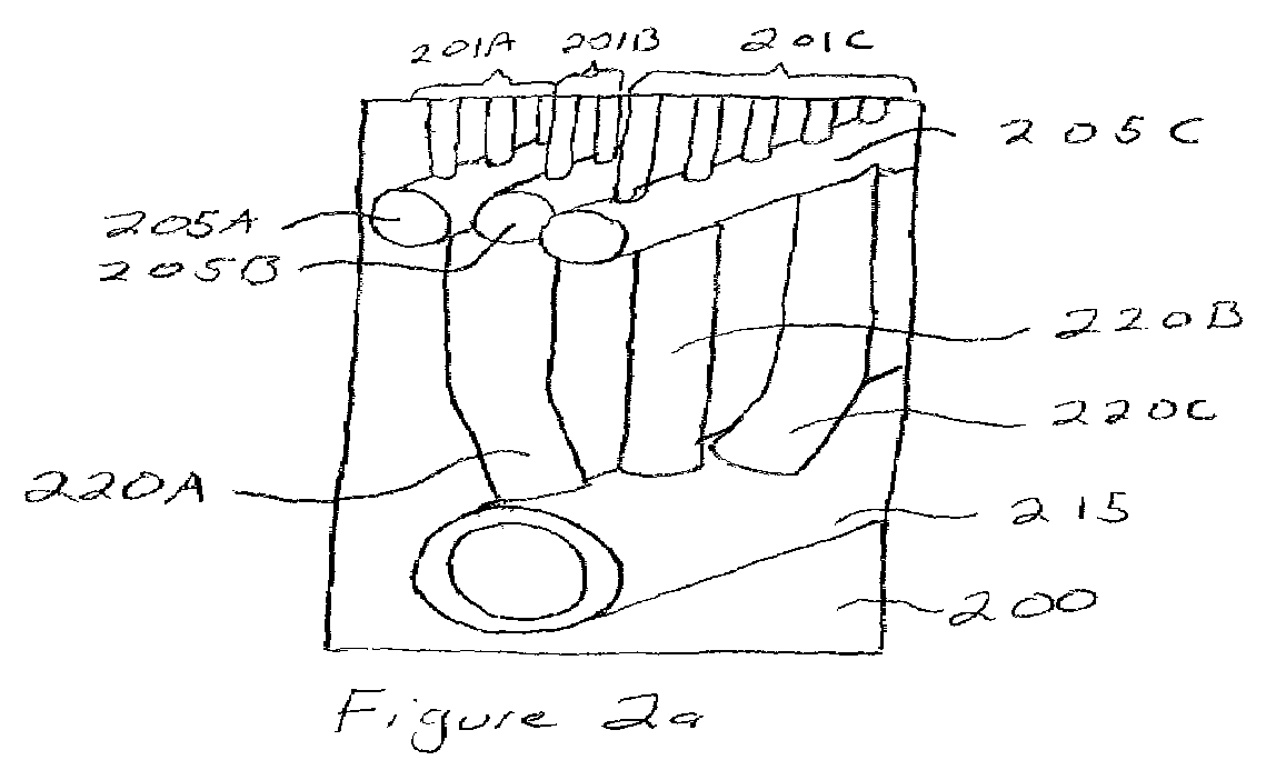
[0033]Referring to FIGS. 2a and 2b, a stepped component thickness with single row header-and-tube assembly 200 that is not subject to bend and attachment failure due to thermal stresses, discussed above, is provided for use in a once-through type horizontal HRSG. FIGS. 2a and 2b are different views of the same assembly 200. In the interest of clarity in the illustration, FIG. 2b only shows a single tube in each tube row 201A–201C. Assembly 200 includes single tube rows 201A–201C, each attached to a common header 205A–205C respectively. Thus, tube row 201A is attached to common header 205A, tube row 201B is attached to common header 205B, and tube row 201C is attached to common header 205C. Such an arrangement may be referred to as a single-row header-and-tube assembly. Each header 205A–205C is connected to a collection manifold 215 via a link pipe 220A–220C. Thus, header 205A is connected to the collection manifold 215 via link pipe 220A, header 205B is connected to the collection m...


PUM


Abstract

A steam generator is disclosed herein. The steam generator includes an inlet manifold, a discharge manifold, a heating gas duct, and at least one once-through heating area in the heating-gas duct. The once-through heating area is formed from multiple single-row header-and-tube assemblies. Each single-row header-and-tube assembly includes a plurality of steam generator tubes connected in parallel, an inlet header connected to the inlet manifold, and a discharge header connected to the discharge manifold. Each inlet header is connected to the inlet manifold by one of multiple first link pipes, and each discharge header is connected to the discharge manifold by one of multiple second link pipes. Each said steam generator tube of each of the single-row header-and-tube assemblies has an inside diameter that is less than an inside diameter of any of the first or second link pipes.

Description

FIELD OF THE INVENTION[0001]The present invention is related to steam generators, and more particularly to horizontal once through heat recovery steam generators.BACKGROUND OF THE INVENTION[0002]Heat Recovery Steam Generators (HRSGs) include evaporator tube rows (multiple tube rows are commonly referred to as tube bundles) that transfer heat from an exhaust-gas stream, such as that from a combustion turbine or other industrial process that produces hot gas, to a fluid inside the evaporator tubes. Horizontal HRSGs employ vertical evaporator tube rows arranged in cross-flow to an exhaust-gas stream that flows in a horizontal direction across the vertical evaporator tubes. An evaporator section on HRSGs typically includes lower manifolds (headers) to distribute water to the bottom of the evaporator tubes, and upper manifolds (headers) to collect a mixture of steam and water from the top of the evaporator tubes.[0003]One type of horizontal HRSG is a circulation type horizontal HRSG. In ...

Claims


Application Information

Patent Timeline
IPC IPC(8): F22D7/00F22B1/18F22B29/06F22B37/14
CPCF22B1/1815F22B29/06F22B37/14
Inventor MASTRONARDE, THOMAS P.
Owner GENERAL ELECTRIC TECH GMBH
Why Eureka
Try Eureka