
Duct unit for air-conditioner

a technology for air conditioners and duct units, applied in ducting arrangements, lighting and heating apparatuses, heating types, etc., can solve the problems of large amount of carbon dioxide exhaust considered a main cause of global warming, low transportation efficiency, and inability to reduce the amount of carbon dioxide exhaust. , to achieve the effect of reducing the radius of curvature, improving the strength of the air-conditioning duct, and being convenient to conn

Inactive Publication Date: 2005-10-25
FUJI KUUCHOU KOUGYOU CO LTD
View PDF7 Cites 58 Cited by
  • Summary
  • Abstract
  • Description
  • Claims
  • Application Information

AI Technical Summary

Benefits of technology

"The present invention provides an air-conditioning duct unit that can be easily folded into a flattened state for transportation and can be easily returned to its original state for use. The duct unit is made up of metal sheets with spin locks curved into a curled shape, which can be joined together to form a rotatable lock joint. The duct unit can be connected to other ducts using connection flanges on the wall portions. The duct unit can also be made more compact by reducing the diameter of the lock joint. A reinforcing flange can be added to prevent deformation of the wall portions. The duct unit can be formed of identical wall members, which improves the assembly process. The technical effects of the invention are a compact duct unit that can be easily transported and easily returned to its original state for use."

Problems solved by technology

In such a case, the transportation efficiency is considerably low and the cost of transportation of duct units is large.
Moreover, the amount of carbon dioxide exhaust considered a main cause of global warming is not negligible due to considerably low energy efficiency.
In construction of high-rise buildings increasing in number recently, a substantial space is required for carrying-in of duct units, a substantially long time is required for lifting, and the cost of transport inside and outside the buildings are large.

Method used


Image

  • Duct unit for air-conditioner
  • Duct unit for air-conditioner
  • Duct unit for air-conditioner

Examples


Embodiment Construction

[0027]The present invention will be described below in detail with reference to the drawings.

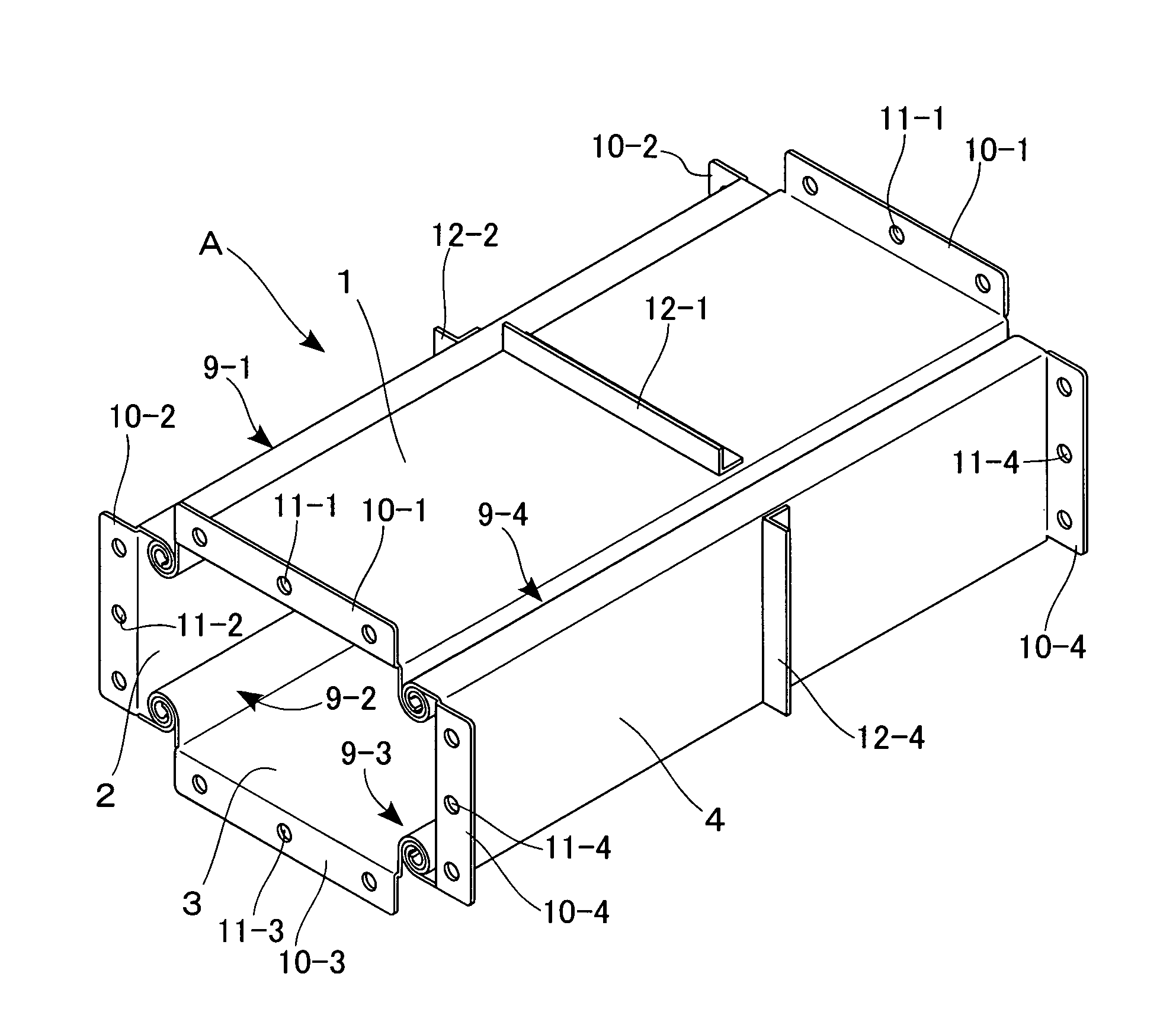
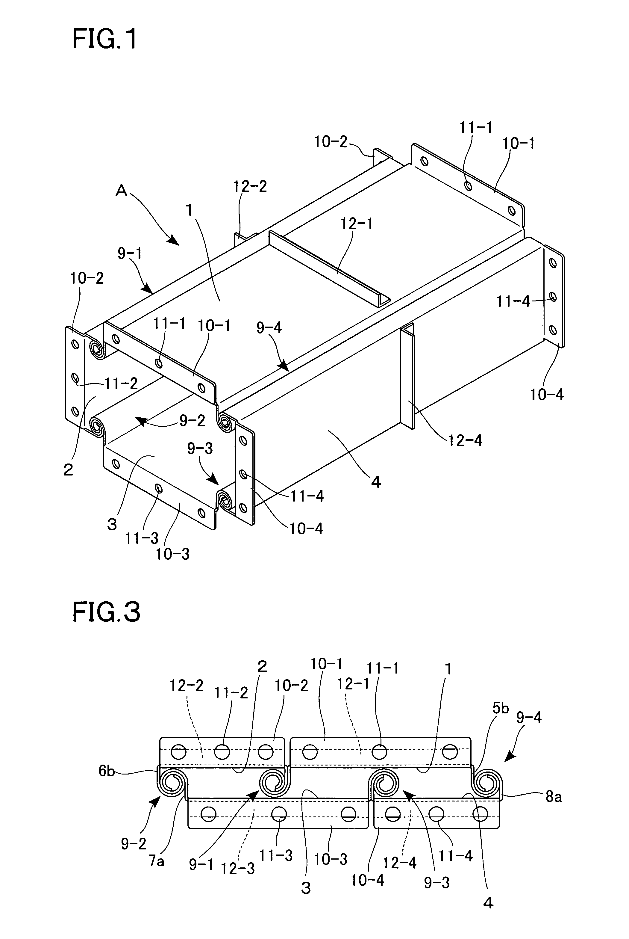
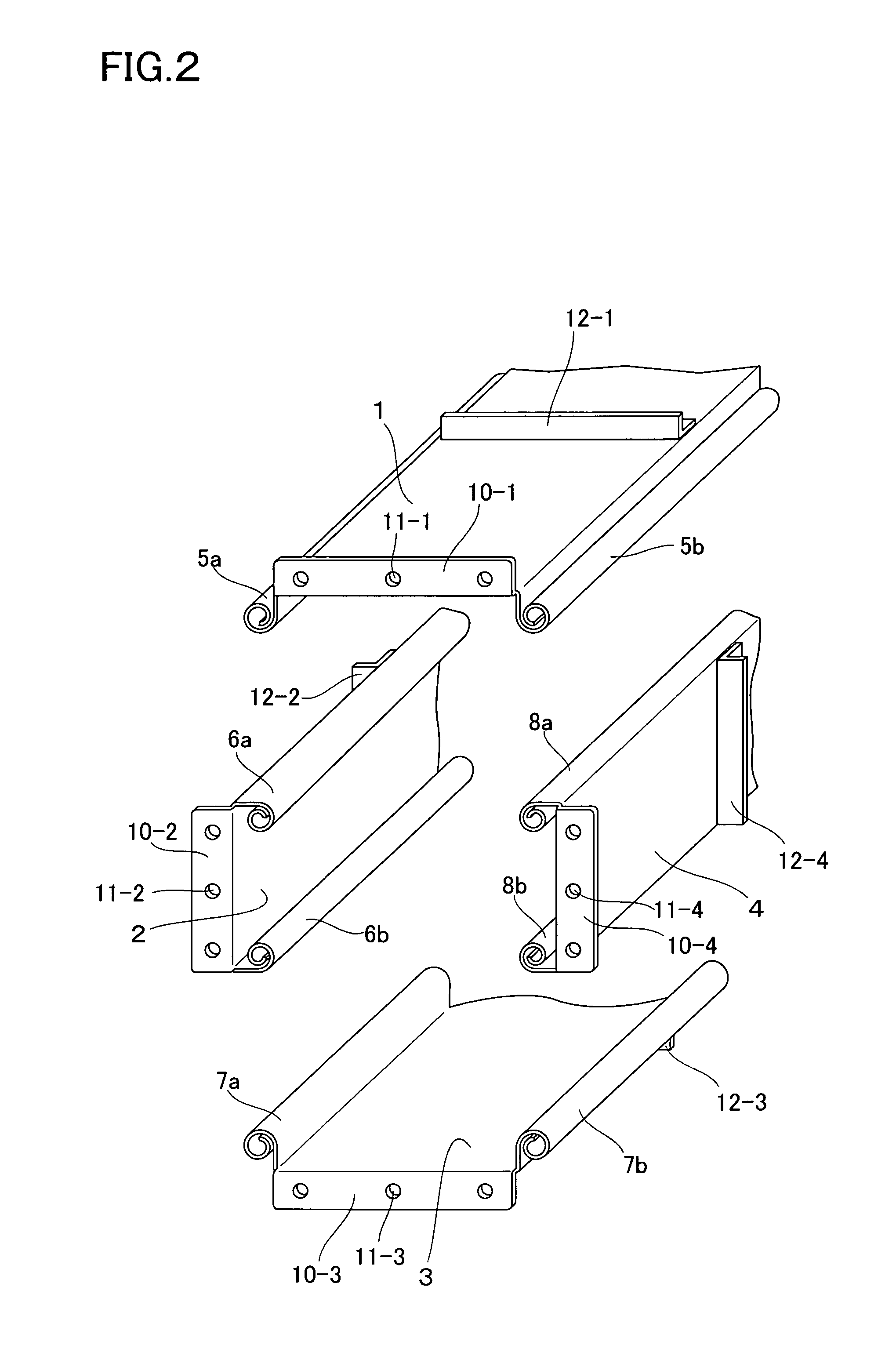
[0028]In FIGS. 1 and 2, a reference symbol A denotes an air-conditioning duct unit which is rectangular in section, and which is formed by four metal sheets processed by a preservative treatment: an upper wall portion 1, a left wall portion 2, a lower wall portion 3 and a right wall portion 4. Spin locks 5 to 8 formed by being curved into a curled shape are provided on the wall portions 1 to 4 at two side edges of the same along the longitudinal direction.

[0029]The spin locks 5 to 8 respectively have small-width flat portions perpendicularly bent from the planer portions in the wall portions 1 to 4, and curved portions having a curled shape, the curved portions being formed continuously from the small-width flat portions. It is preferred that the spin locks 5 to 8 have flat portions. However, if the radius of curvature of the curved portions is large, the formation of the flat portions is no...


PUM


Abstract

An object of the present invention is to provide an air-conditioning duct unit capable of being made compact when transported to largely reduce the cost of transport inside and outside a building as well as the cost of transportation by a truck.A duct unit A of the present invention has upper and lower wall portions 1 and 3 and right and left wall portions 2 and 4 formed of metal sheets, and spin locks curved into a curled shape, the spin locks being provided on the wall portions 1 to 4 at two side edges of the same along the longitudinal direction. One of the pair of spin locks provided on each adjacent pair of the wall portions is inserted in the other to form one of lock joints 9-1 to 9-4 rotatably. The wall portions 1 to 4 are linked so that the duct unit A can be changed in shape. Consequently, the duct unit can be folded so as to be flattened.

Description

CROSS-REFERENCE TO RELATED APPLICATION[0001]This application is a National Stage entry of International Application No. PCT / JP03 / 04094 filed Mar. 31, 2003. The disclosure of the prior application is hereby incorporated herein in its entirety by reference.TECHNICAL FIELD[0002]The present invention relates to an air-conditioning duct unit formed in such a manner that flanges provided in end surfaces are connected to each other. More particularly, the present invention relates to an air-conditioning duct unit capable of being transported in a flattened state to a workplace.BACKGROUND ART[0003]In most cases, an air-conditioning duct is installed in the ceiling or under the floor of a building by connecting a plurality of duct units to a necessary length. Air-conditioning ducts have a rectangular shape or a circular shape. A duct in rectangular shape is generally called a rectangular duct and has, in principle, button-punch snap locks or Pittsburgh locks in at least two places. For conne...

Claims


Application Information

Patent Timeline
Patent Type & Authority Patents(United States)
IPC IPC(8): F16L9/00F24F13/02F16L23/02
CPCF16L9/003F16L23/14F24F13/02F24F13/0209Y10S138/04
Inventor KAJINO, ISAMU
Owner FUJI KUUCHOU KOUGYOU CO LTD
Learn More