Ferrule assembly having highly protruding optical fibers and an associated fabrication method

a technology of ferrules and assemblies, which is applied in the direction of optics, instruments, optical light guides, etc., can solve the problems of insufficient end portions of optical fibers that protrude beyond the front face of ferrules, and insufficient optical fiber protrusion of this magnitude, etc., to achieve efficient, precise and repeated effects

Inactive Publication Date: 2005-10-25
CORNING OPTICAL COMM LLC
View PDF8 Cites 79 Cited by
  • Summary
  • Abstract
  • Description
  • Claims
  • Application Information

AI Technical Summary

Benefits of technology

[0011]A ferrule assembly having highly protruding optical fibers and a corresponding method of efficiently, precisely and repeatedly fabricating ferrule assemblies having highly protruding optical fibers are provided according to the present invention. According to one aspect of the present invention, a ferrule assembly is provided that includes a plurality of optical fibers extending at least about 3.5 μm, taking account of customary manufacturing tolerances, beyond all portions of the front face. The end portions of the optical fibers of the ferrule assembly may also be substantially coplanar in that the end portions of the optical fibers differ in position from one another by no more than about 100 nm according to one embodiment. Thus, a pair of ferrule assemblies of the present invention may be mated such that direct physical contact is maintained between the end portions of the optical fibers even while the ferrule deforms and the optical fibers withdraw as a result of environmental conditions, loading or the like.
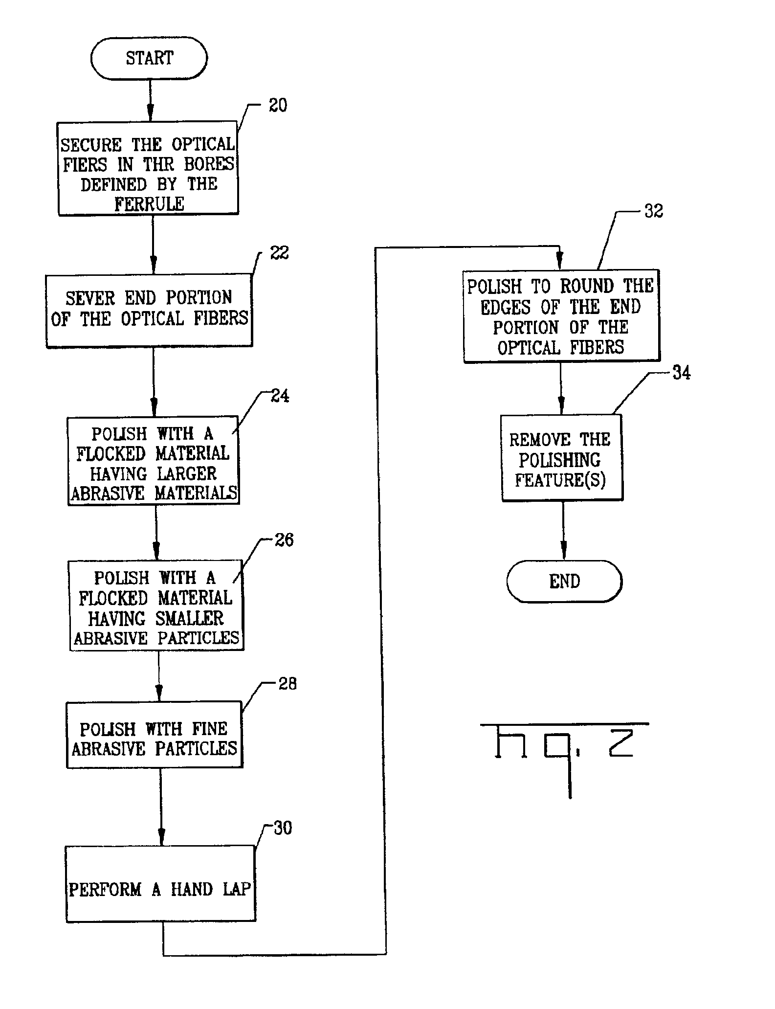
[0013]The end portions of the optical fibers may also be polished with a flocked material. For example, the end portions of the optical fibers may be polished with a flocked material, typically a fine flocked material, after the end portions of the optical fibers have been lapped, such as to round the edges of the optical fibers. In addition, the end portions of the optical fibers may be polished with a coarse flocked material prior to lapping the end portions of the optical fibers to reduce the protrusion of the optical fibers and to remove at least some or all of the epoxy from the front face of the ferrule. Generally, the coarse flocked material has larger abrasive particles than the flocked material with which the end portions of the optical fibers are polished following lapping of the end portions of the optical fibers. According to this aspect of the present invention, the method efficiently fabricates a ferrule assembly having protruding optical fibers since the end portions of the optical fibers generally remain extended beyond the front face of the ferrule during the entire process, thereby obviating the need to grind or polish the end portions of the optical fibers flush with the front face of the ferrule prior to preferentially etching the front face of the ferrule relative to the end portions of the optical fibers as practiced by conventional techniques.
[0015]Regardless of the amount of protrusion, the end portions of the optical fibers of the ferrule assembly according to one aspect of the present invention are substantially co-planar in that the end portions differ in position from one another by no more than 100 nm. Additionally, the end portion of each optical fiber preferably differs in position from the end portions of the immediately adjacent optical fibers by no more than 50 nm. By utilizing fine abrasive particles, the core dip is also reduced, such as to less than 10 nm, as well as the possibility of core cracking for multimode optical fibers. By protruding at least about 3.5 μm beyond the front face of the respective ferrule and, in some embodiments, by exhibiting improved co-planarity and reduced core dip, a pair of ferrule assemblies may be mated so as to maintain the end portions of corresponding pairs of optical fibers in direct physical contact, even as the environmental conditions, loading and other factors vary.
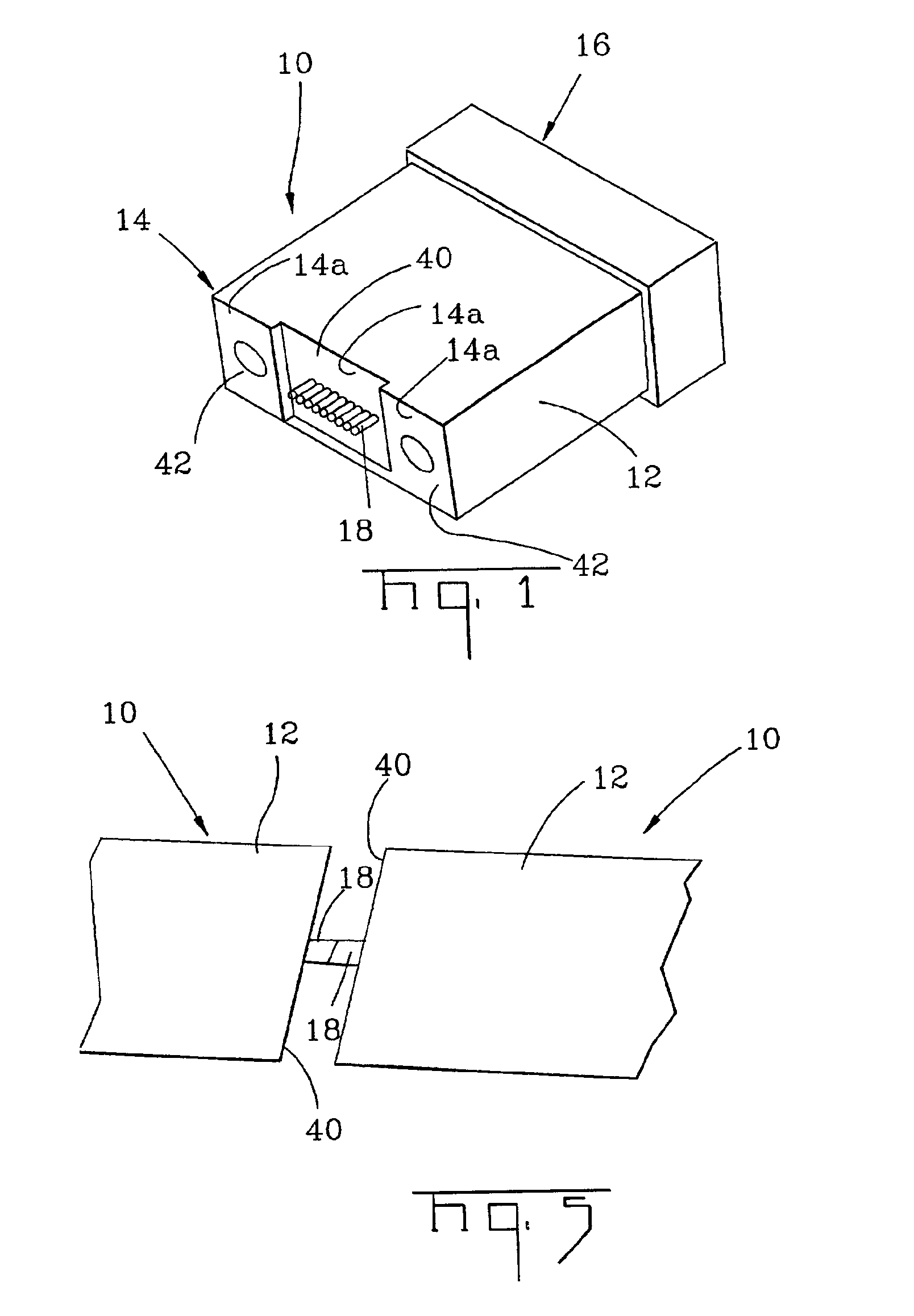
[0016]According to one aspect of the present invention, the front face of the ferrule may at least initially include at least one polishing feature to further improve the efficiency of the fabrication process and quality and repeatability of the resulting ferrule assemblies. In addition to the polishing feature, the front face of the ferrule may also include a first portion through which the bores at least partially open. The polishing feature is offset with respect to a first portion. For example, the polishing feature may be a recessed portion having a reference surface, such as a planar or a curved reference surface, that extends in a rearward direction from the first portion of the front face. Alternatively, the polishing feature may be at least one pedestal having a planar surface that extends outwardly from the first portion of the front face of the ferrule, such as by a distance approximately equal to the desired protrusion of the optical fibers. In this embodiment, the ferrule can include first and second pedestals positioned on opposite sides of the first portion of the front face and extending outwardly therebeyond. For example, the plurality of bores may open through the front face along a reference line extending between opposite sides of the ferrule body. As such, the first and second pedestals of this embodiment may be positioned proximate the opposite sides of the ferrule body along the reference line.
[0021]While reducing the protrusion of at least one optical fiber according to one embodiment, the spacing between the line of intersection and the at least one optical fiber may be monitored and the protrusion of the at least one optical fiber may continue to be reduced at least until the spacing between the line of intersection and the at least one optical fiber is no more than a predefined spacing. Since the spacing between the line of intersection and the optical fibers provides a measure of the amount of protrusion of the at least one optical fiber, the predefined spacing may be selected to correspond to a desired protrusion of the at least one optical fiber. By halting any further reduction in the protrusion of the at least one optical fiber once the predefined spacing is detected, the resulting ferrule will have an optical fiber with the desired protrusion. Moreover, by monitoring the spacing between the line of intersection and the at least one optical fiber, such as with a vision system, the method of this aspect of the present invention can reliably fabricate ferrules having optical fibers with a desired protrusion without requiring a relatively expensive interferometer to measure the protrusion of the optical fibers as is required by most conventional techniques. Additionally, the angle between the line of intersection and a reference line extending through the plurality of optical fibers may also be monitored since this angle corresponds to the angle at which the end portions of the optical fibers are being polished.
[0022]According to the present invention, ferrule assemblies are therefore provided having highly protruding optical fibers, such as optical fibers that protrude by about 3.5 μm to about 5 μm or more beyond the front face of the ferrule. In addition, ferrule assemblies having protruding optical fibers that are substantially co-planar, such as optical fibers having end portions that vary by no more than about 100 nm, are also provided. In mating a pair of multifiber connectors, direct physical contact between the end portions of corresponding pairs of optical fibers can be therefore be established and maintained. In addition, by polishing the end portions of the optical fibers to establish the desired protrusion without ever having to remove substantial portions of the front face of the ferrule one can increase the fabrication efficiency, particularly in instances in which the ferrule includes at least one polishing feature to define the desired protrusion distance.

Problems solved by technology

Unfortunately, the amount by which the end portions of the optical fibers protrude beyond the front face of a ferrule is sometimes inadequate.
In these instances, portions of the front faces of the ferrules of a pair of mated multifiber connectors may make contact, potentially creating a gap between the end portions of the corresponding optical fibers.
A 1 μm to 3 μm protrusion distance may initially be adequate; however, optical fiber protrusion of this magnitude may become insufficient for several reasons.
The presence of moisture and humidity may also cause the optical fibers to somewhat withdraw into the ferrule, while correspondingly causing the front face of the ferrule to swell.
In addition, dust, dirt or other debris may accumulate on the front face of the ferrule.
Moreover, the application of mechanical loads to the optical fibers may further cause the ferrule to deform.
The end portions of the optical fibers may therefore be separated or spaced from one another, thereby undesirably increasing the attenuation and reflectivity experienced by the signals transmitted via the optical fibers.
These problems are exacerbated as the area of the potential contact region between the front faces of the mated ferrules, i.e., the area across which the front faces of the mated ferrules would make contact in the absence of fiber protrusion, increases.
In this regard, the problems are exacerbated since more opportunities are provided for the disadvantageous accumulation of dust, dirt or other debris in the area of the potential contact region.
The issues with respect to the accumulation of dust, dirt or other debris are particularly problematic in instances in which the potential contact region includes the guide pin holes since a greater percentage of dust, dirt and other debris accumulates about the guide pin holes than upon other portions of the front face of the ferrule.
Additionally, if the potential contact region is a large area, the undesirable effects of ferrule deformation and swelling as a result of exposure to moisture and humidity are increased.
Conventional processes are generally unable to establish co-planarity any closer than about 250 nm, causing a variance in the protrusion distance.
As will be apparent, as the variance in protrusion of the fibers increases, the difficulty in establishing direct physical contact between the end portions of each corresponding pair of optical fibers also increases.
The preferential etching of the core with respect to the cladding causes core dip that further reduces the likelihood of the desired fiber-to-fiber contact and, in particular, the likelihood of physical contact between the cores of the corresponding pairs of optical fibers.
The failure to establish physical contact between the cores of the corresponding pairs of optical fibers is particularly disadvantageous since the signals are transmitted through the cores of the optical fibers.
Multifiber connectors can suffer additional problems in instances in which the multifiber connectors are mounted upon multimode optical fibers.
In this regard, the relatively coarse abrasive particles utilized in conventional processes for polishing the end portions of the optical fibers and the front face of the ferrule in order to attain the desired protrusion distance can cause or at least exacerbate core cracking of the multimode optical fibers.
While some types of core cracking can be remedied by further processing, this additional processing only increases the time and cost required to fabricate the multifiber connector.
Other types of core cracking cannot be corrected, however, and the multifiber connector must, instead, be scrapped.

Method used


Image

  • Ferrule assembly having highly protruding optical fibers and an associated fabrication method
  • Ferrule assembly having highly protruding optical fibers and an associated fabrication method
  • Ferrule assembly having highly protruding optical fibers and an associated fabrication method

Examples


Embodiment Construction

[0033]The present invention now will be described more fully hereinafter with reference to the accompanying drawings, in which preferred embodiments of the invention are shown. This invention may, however, be embodied in many different forms and should not be construed as limited to the embodiments set forth herein; rather, these embodiments are provided so that this disclosure will be thorough and complete, and will fully convey the scope of the invention to those skilled in the art. Like numbers refer to like elements throughout.

[0034]A ferrule assembly having highly protruding optical fibers and an associated method of fabricating ferrule assemblies are provided according to the present invention. As shown in FIG. 1, the ferrule assembly 10 includes a multifiber ferrule 12 extending between a front end 14 having a multi-section front face and an opposed rear end 16. The front face comprises surfaces 14a that are generally transverse with respect to the longitudinal axes of the op...


PUM


Abstract

A ferrule assembly having highly protruding optical fibers and a corresponding method of efficiently, precisely and repeatedly fabricating the ferrule assemblies are provided. In this regard, a ferrule assembly is provided that includes a plurality of optical fibers extending at least about 3.5 μm beyond the front face. The end portions of the optical fibers of the ferrule assembly may also be substantially coplanar with the end portions of the optical fibers differing in position from one another by no more than 100 nm. The ferrule assembly may be efficiently fabricated by polishing the optical fibers to a desired protrusion without first grinding or polishing the optical fibers to be flush with the front face of the ferrule. The ferrule assembly may be even more efficiently fabricated in instances in which the ferrule includes at least one polishing feature, such as an outwardly extending pedestal or a recessed portion.

Description

FIELD OF THE INVENTION[0001]The present invention relates generally to ferrule assemblies having highly protruding optical fibers, such as optical fibers that protrude beyond the front face of a ferrule by at least about 3.5 μm. The present invention also relates to improved methods for fabricating ferrule assemblies and, in particular, to methods for fabricating ferrule assemblies having highly protruding optical fibers in which the optical fibers extend beyond the front face of the ferrule during the entire fabrication process.BACKGROUND OF THE INVENTION[0002]In order to effectively mate multifiber connectors, the end portions of the plurality of optical fibers upon which one connector is mounted must generally be brought into physical contact with the end portions of corresponding optical fibers upon which another connector is mounted. Direct physical contact between the end portions of corresponding pairs of optical fibers is particularly desirable for those multifiber connector...

Claims


Application Information

Patent Timeline
Patent Type & Authority Patents(United States)
IPC IPC(8): G02B6/38G02B6/40G02B6/00
CPCG02B6/38G02B6/3863G02B6/3885
Inventor LUTHER, JAMES P.KNECHT, DENNIS M.TRAN, HIEU V.ELKINS, II, ROBERT B.
Owner CORNING OPTICAL COMM LLC
Why Eureka
Try Eureka