Hydrogen use in a GTL plant

Inactive Publication Date: 2005-10-25
CONOCOPHILLIPS CO
View PDF31 Cites 66 Cited by
  • Summary
  • Abstract
  • Description
  • Claims
  • Application Information

AI Technical Summary

Benefits of technology

[0010]FIG. 1 is a simplified block flow diagram of a hydrocarbon gas to liquid plant in accordance with the present invention, wherein a

Problems solved by technology

However, natural gas reserves have been found in remote areas where it is uneconomical to develop the reserves due to the lack of local markets for the gas and the high co

Method used


Image

  • Hydrogen use in a GTL plant
  • Hydrogen use in a GTL plant

Examples


Embodiment Construction

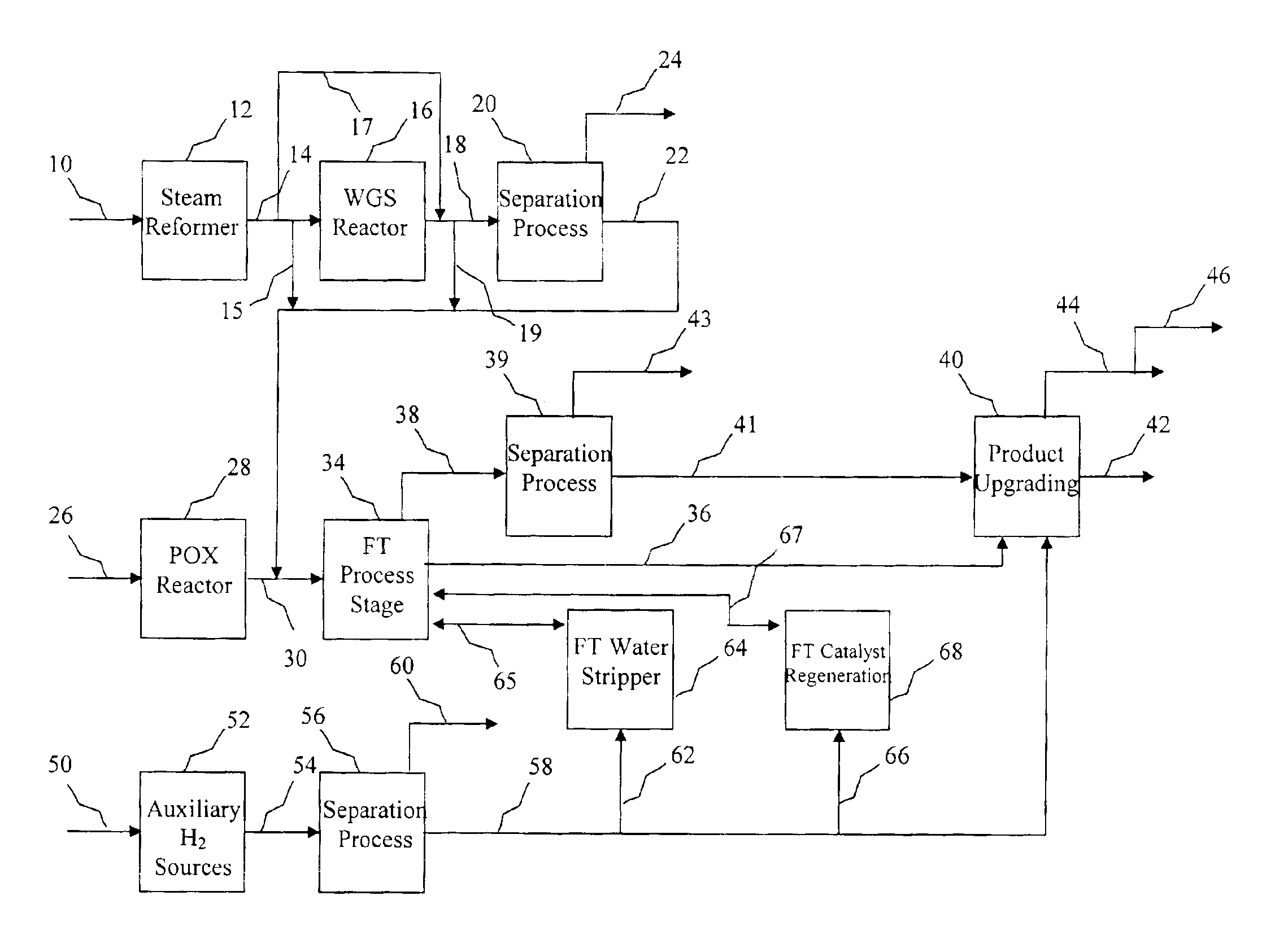
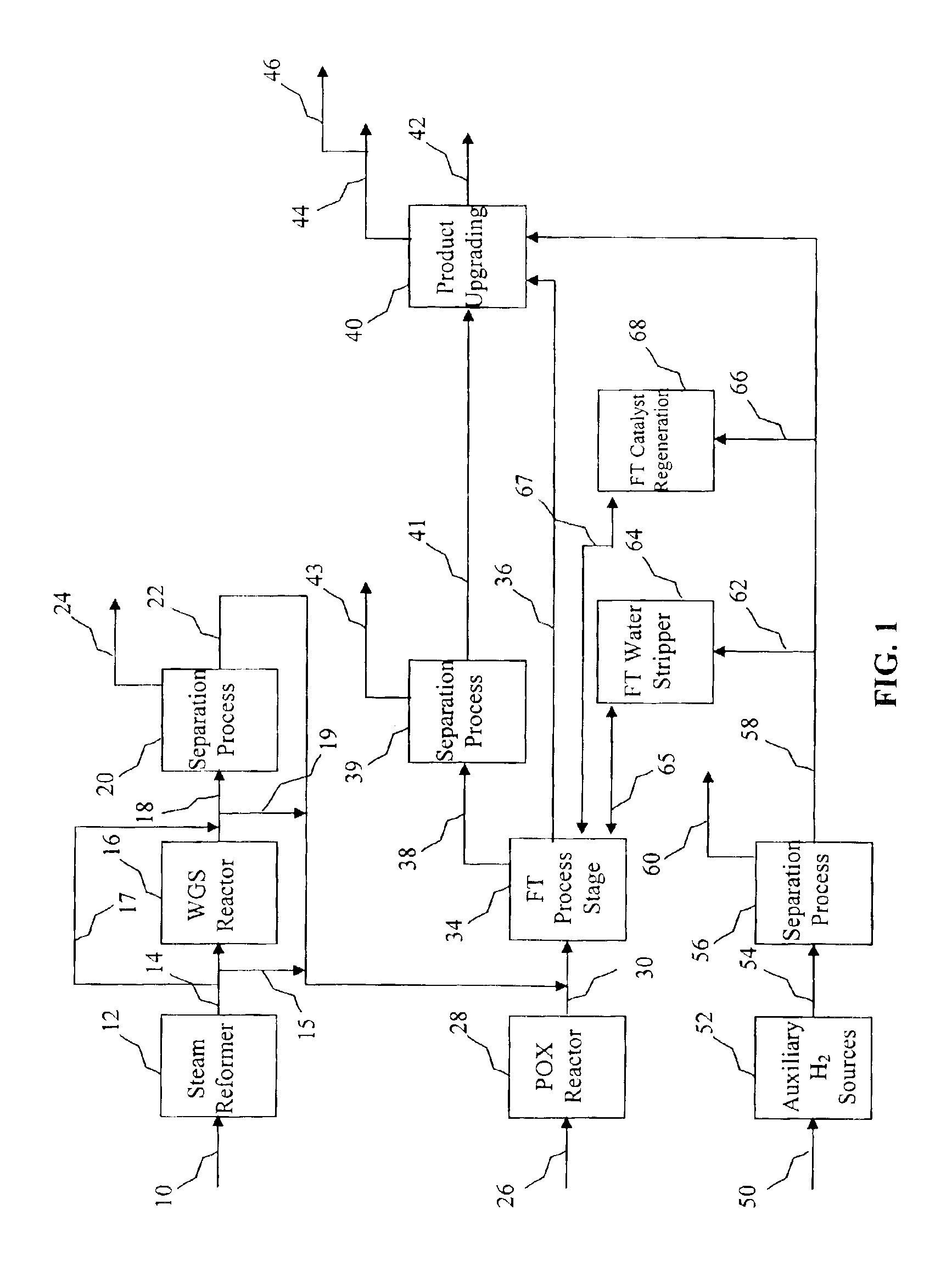
[0011]The present invention provides a process for managing hydrogen generated in a plant for converting natural gas to useful liquid products, thereby making the GTL plant more cost effective. FIG. 1 depicts a hydrogen-containing stream produced by a steam reformer being introduced to a feed stream of a FT process stage. As used herein, process stage refers to a process stage comprising one or more reactors, wherein a given conversion of syngas to hydrocarbons is achieved. In a multi-stage process, a plurality of process stages are arranged in series such that a subsequent or downstream stage receives unreacted reactants (e.g., syngas) and some of the products from a prior or upstream stage and further converts the unreacted reactants to hydrocarbons, thereby increasing the overall percent conversion of reactants as they pass from stage to stage until a final desired conversion percentage is obtained. Furthermore, reaction conditions typically vary from stage to stage, and the pres...


PUM

PropertyMeasurementUnit
Concentrationaaaaaaaaaa
Ratioaaaaaaaaaa

Abstract

The present invention provides a process for managing hydrogen in a hydrocarbon gas to liquid plant. The process includes passing a syngas feed stream produced by a partial oxidation reactor to a Fischer-Tropsch reactor, thereby converting the syngas to hydrocarbon liquids. The hydrogen management process further includes passing a second hydrogen rich stream produced by an auxiliary source to a hydrogen user such as an FT water stripper, an FT catalyst regeneration unit, and an FT product upgrading unit. The auxiliary source could be a process for converting hydrocarbons to syngas, a process for converting hydrocarbons to olefins, a process for converting hydrocarbons to aromatics, a process for catalytically dehydrogenating hydrocarbons, a process for catalytically cracking hydrocarbons, a process for refining petroleum, and a process for converting hydrocarbons to carbon filaments.

Description

CROSS-REFERENCE TO RELATED APPLICATIONS[0001]Not applicable.STATEMENT REGARDING FEDERALLY SPONSORED RESEARCH OR DEVELOPMENT[0002]Not applicable.REFERENCE TO A MICROFICHE APPENDIX[0003]Not applicable.FIELD OF THE INVENTION[0004]This invention generally relates to the production of hydrocarbons. More specifically, the invention relates to a process for managing hydrogen in a gas to liquid (GTL) plant.BACKGROUND OF THE INVENTION[0005]Large quantities of natural gas are available in many areas of the world, and natural gas is predicted to outlast oil reserves by a significant margin. However, natural gas reserves have been found in remote areas where it is uneconomical to develop the reserves due to the lack of local markets for the gas and the high cost of transporting the gas to distant markets. This high cost is often related to the extremely low temperatures needed to liquefy the highly volatile gas during transport. An alternative is to locally convert the natural gas to liquid hyd...

Claims


Application Information

Patent Timeline
IPC IPC(8): C01B3/00C01B3/38C10G2/00
CPCC01B3/382C10G2/30C10G2/32C10G2/332C10G2/40C01B2203/062Y02P20/584
Inventor ESPINOZA, RAFAEL L.MOHEDAS, SERGIO R.GOODWIN, III, RALPH T.LANDIS, STEPHEN R.BELT, BARBARA A.
Owner CONOCOPHILLIPS CO
Why Eureka
Try Eureka