Equalization for a multi-axis imaging system

a multi-axis imaging and equalization technology, applied in the direction of optical radiation measurement, radiation control devices, instruments, etc., can solve the problems of ineffective use of trans-illumination, present new challenges for illumination, and prior art epi-illumination techniques cannot be used

Inactive Publication Date: 2005-10-25
DMETRIX INC
View PDF14 Cites 11 Cited by
  • Summary
  • Abstract
  • Description
  • Claims
  • Application Information

AI Technical Summary

Problems solved by technology

While the use of electronic image detection offers electronic capture of an image and the possibility of reducing the size of an imaging system, effective, compact epi-illumination has remained a challenge.
The recent development of miniaturized microscope arrays presents new challenges for illumination.
Indeed, the multiplicity of lenslets arranged in an array and the small dimensions of the array suggest that prior art epi-illumination techniques cannot be used.
Yet, a principal application for miniature microscope arrays is to image specimens, such as biological microarrays for protein analysis, that are sufficiently opaque that trans-illumination cannot be used effectively.
These variations in source radiance and detector responsivity and flux-dependent DC offset can create pixel-to-pixel brightness errors in the images produced by a microscope array.

Method used


Image

  • Equalization for a multi-axis imaging system
  • Equalization for a multi-axis imaging system
  • Equalization for a multi-axis imaging system

Examples


first embodiment

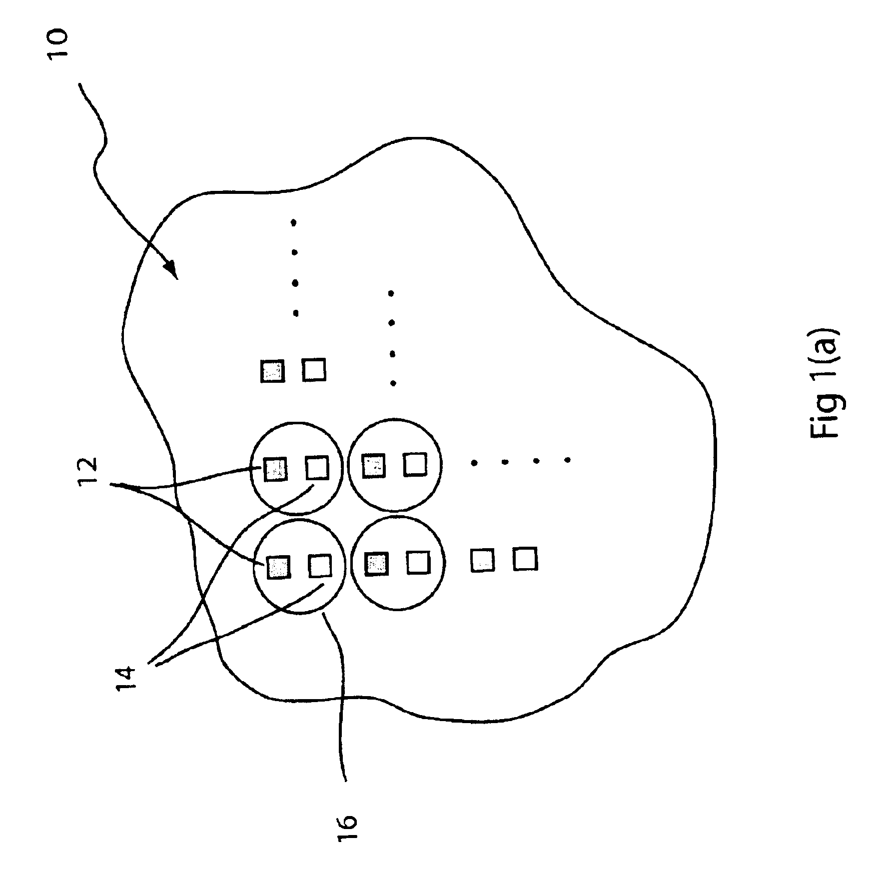
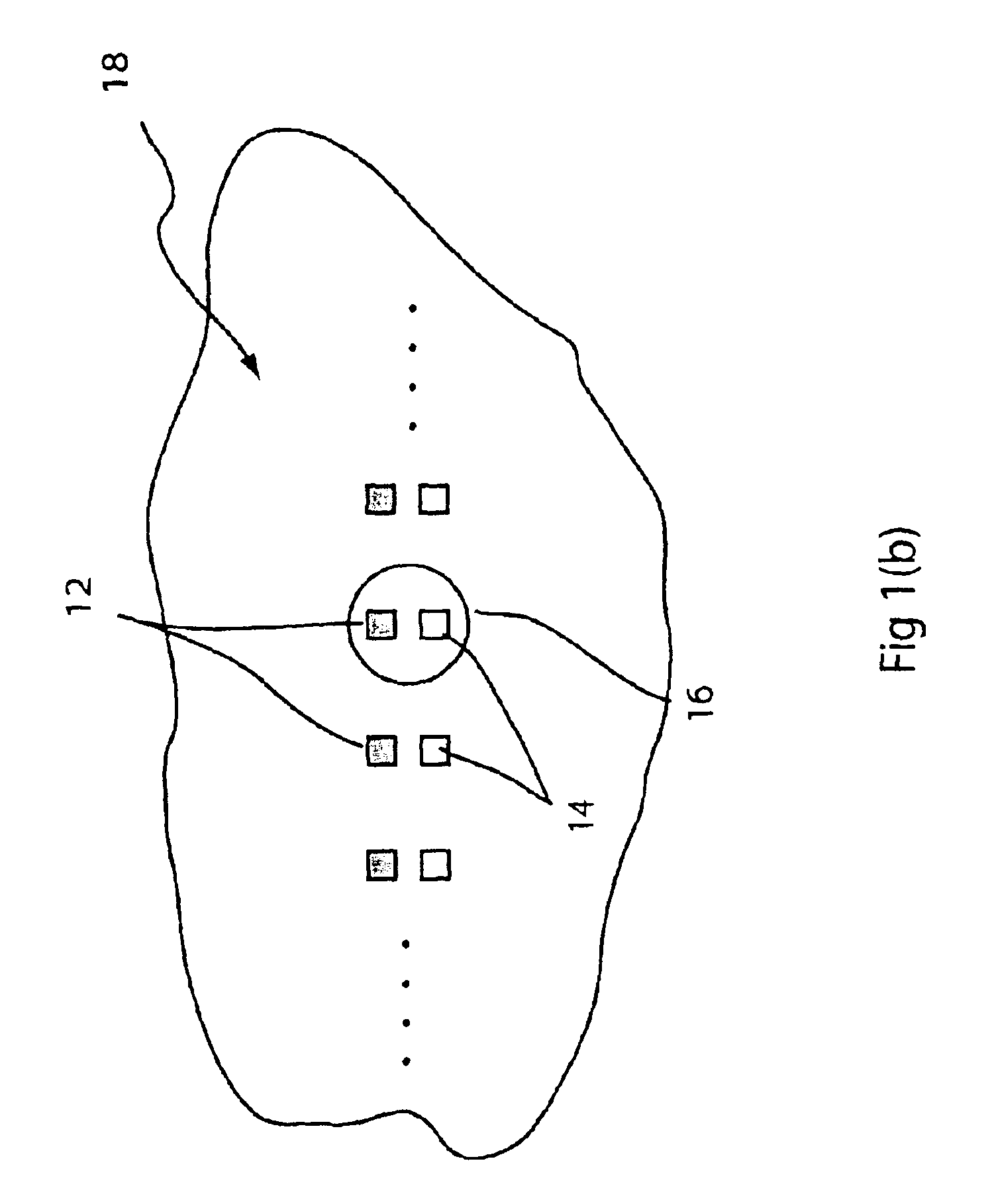
[0040]While this first embodiment does not provide optimal light efficiency, it is simple, compact, and straightforward to manufacture. It can be implemented with either a one-dimensional array, as shown in FIG. 1(b) or a two dimensional array, as shown in FIG. 1(a). To increase light efficiency, multiple detectors surrounding the light source within the central lobe of the image could be used. Also, the optical system can be designed to have desired aberrations so as to produce a non-symmetric PSF and maximize the light irradiating the detector area. As will be understood by a person skilled in the art, there are various ways of accomplishing this, including, for example, forming lenses with aspherical surfaces and decentering the elements of the optical system.

[0041]A second embodiment 40 of a one-dimensional integrated source and detector array illumination system, shown in FIG. 3, uses a diffraction element to separate the illumination light from the image light at image plane. ...

third embodiment

[0042]In a third embodiment, conjugate points on the image plane can be formed by a Wollaston prism. As shown in FIG. 4, a quarter wave plate 44 may be placed in front of a Wollaston prism 46 at an angle to the two eigenaxes thereof so that the optical pathway is split into two pathways having respectively orthogonal polarizations and respective angles of refraction, as indicated by the dot 48 and arrow 50. This requires either that the source 36 produce light that is linearly polarized in the direction represented by dots 48, or that a linear polarizer 49 be used to produce such linear polarization. The source light is then circularly polarized in one direction by the quarter wave plate, circularly polarized in the opposite direction upon reflection from the object, then linearly polarized in the direction of arrows 50 by the quarter wave plate. Thus, this arrangement creates two conjugate points in the image plane that correspond to a light source 34 and photodetector 36, respecti...

second embodiment

[0046]The embodiments of FIGS. 2-5 can also be used in a confocal mode, as shown with respect to the second embodiment in FIG. 6. In this case, a stop is provided with an array of pinhole apertures 54, one for each detector 34, and with conjugate apertures for the light sources 36. The image of each source, which is essentially a point source, is conjugated with the object plane. After reflection from the object, the light is imaged onto a corresponding pinhole aperture 54. The amount of light that passes through the aperture is closely related to the focus of the image and can be used to gauge the distance of the object surface to the focal position. If the object and the light beam are then moved with respect to one another, the profile of the object can thereby be determined. By providing a linear array of source-detector pairs and scanning the object in a direction perpendicular to the array, rapid confocal scanning can be achieved. Depending on the sources and detectors, the ex...


PUM


Abstract

An imaging system with an integrated source and detector array. A plurality of light detectors are arranged in an array and a corresponding plurality of light sources are arranged in an array in an epi-illumination system so that light radiated from a point on the object illuminated by a given source is detected by a corresponding detector. An optical system is disposed so as to illuminate an object with light from the source array and image the object on the detector array. Ordinarily, the sources and detectors are coplanar and, preferably, are fabricated or at least mounted on the same substrate. In one embodiment the Airy pattern of the point response of the optical system encompasses both a detector and corresponding light sources. In another embodiment, the optical pathway is split by a diffractive element to produce conjugate points corresponding to light sources and their respective detectors. In a further embodiment, the pathway is split by a Wollaston prism. In yet another embodiment where the illumination and image light have different wavelengths, the pathway is split by dispersion. Another embodiment comprises a power supply connected to the plurality of light sources, a signal conditioning circuit for receiving and digitizing output signals from the light detectors so as to produce a respective set of output values, and an equalizing system for equalizing the output values for a given input radiance.

Description

[0001]This application is a continuation-in-part of U.S. patent application Ser. No. 10 / 158,633, filed May 30, 2002, which is incorporated herein by reference in its entirety.FIELD OF THE INVENTION[0002]This invention relates to illumination for optical imaging systems, particularly to an integrated detector and source array for epi-illumination in an imaging system, and more particularly in miniature microscope arrays.BACKGROUND OF THE INVENTION[0003]In an imaging system, adequate and appropriate illumination of the object to be imaged is essential. There must be enough light provided to the object to permit a viewer or detector to discern features of the object in the image thereof. In addition, the manner in which the light is provided to the object makes a difference in what features can be detected and the contrast with which they are imaged.[0004]The way in which illumination is provided is particularly important in a microscope. If the object is opaque, it must be illuminated...

Claims


Application Information

Patent Timeline
Patent Type & Authority Patents(United States)
IPC IPC(8): G02B21/00G02B21/36H01L27/00H01L27/146
CPCG02B21/0004G02B21/0032G02B21/0036G02B21/004G02B21/0068G02B21/0076G02B21/008G02B21/0096G02B21/365H01L27/14625
Inventor OLSZAK, ARTUR G.LIANG, CHEN
Owner DMETRIX INC
Why Eureka
Try Eureka