Dual loop feedforward power amplifier

a power amplifier and feedforward loop technology, applied in amplifiers, amplifiers with semiconductor devices/discharge tubes, electrical devices, etc., can solve the problems of introducing complexity to overall amplifier adjustment, additional cost, and complexity, and achieving small improvement in performance, and is typically not deemed worth the extra complexity and cost of utilizing multiple feedforward loops

Inactive Publication Date: 2005-10-25
INTEL CORP
View PDF14 Cites 25 Cited by
  • Summary
  • Abstract
  • Description
  • Claims
  • Application Information

AI Technical Summary

Problems solved by technology

One possible source of such cross-channel interference is known as intermodulation distortion (IMD), which may result when two or more signals of different frequencies are mixed.
For example, if two carriers of different frequencies are amplified using a non-linear amplifier, spurious outputs occur at the sum and difference of integer multiples of the original carrier frequencies.
The additional loops typically have additional phase and gain controls that introduce complexity to overall amplifier adjustment, as well as additional cost.
Typically any small improvement in performance obtained, is typically not deemed worth the extra complexity and cost of utilizing multiple feedforward loops.
Intermodulation distortion tends to cause problems in transmitters that amplify and send out multicarrier signals.
The intermodulation distortion often falls in the spectrum between two of the carrier signals, and is difficult to filter out, because such a filter would likely also filter out the carrier signal, removing that signal and the associated data from the signal that is ultimately amplified by the power amplifier.
However, even with the high-precision components used in the amplifier, the error signal in reality can not completely cancel the spurious components generated by main amplifier 110.
In general, complete cancellation requires that the error correction signal be maintained with greater than 0.5 degrees phase accuracy and 0.1 dB amplitude accuracy which is difficult to achieve in production.
The feed-forward technique can be used in a multi-carrier power amplifier to effectively suppress intermodulation products, but at the cost of lower power efficiency and a high demand on complexity and component cost.
In particular, high power multi-carrier power amplifiers are difficult to master in production.
In addition some distortion typically remains at the output of the feedforward power amplifier.
In addition to environmental and aging factors, the observed intermodulation distortion (IMD) performance of a power amplifier is sensitive to changes in output power, the number of carriers and their frequency separation.
Under these conditions, the automatic control system provides an incorrect, or delayed, estimate of the phase and amplitude adjustments used in the feedforward amplifier, and as a result, the IMD performance is degraded.
Should a different input signal be used, the characteristics of the input signal vary over time, or the components age or degrade over time, the amplifier will not maintain adequate performance.
This switching introduces additional errors into the feedforward amplifier that could prevent such a topology from being applicable to certain applications.

Method used


Image

  • Dual loop feedforward power amplifier
  • Dual loop feedforward power amplifier
  • Dual loop feedforward power amplifier

Examples


Embodiment Construction

[0050]In the following description, reference is made to the accompanying drawings which form a part hereof, and in which is shown by way of illustration, a specific embodiment in which the invention may be practiced. It is to be understood that other embodiments may be utilized and structural changes may be made without departing from the scope of the present invention.

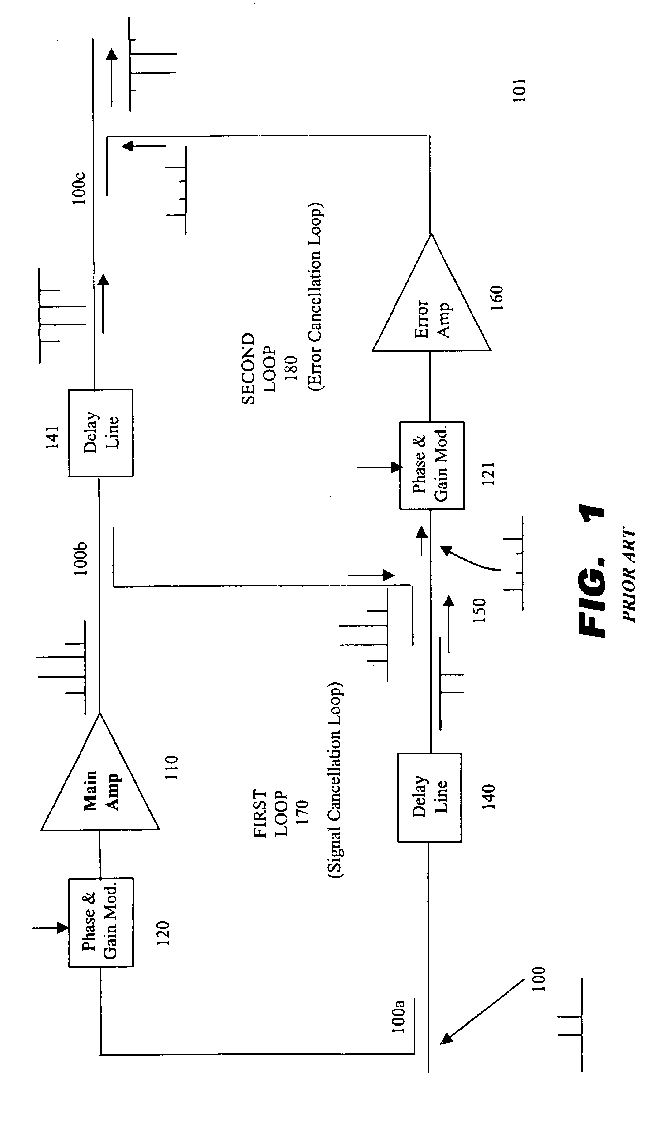
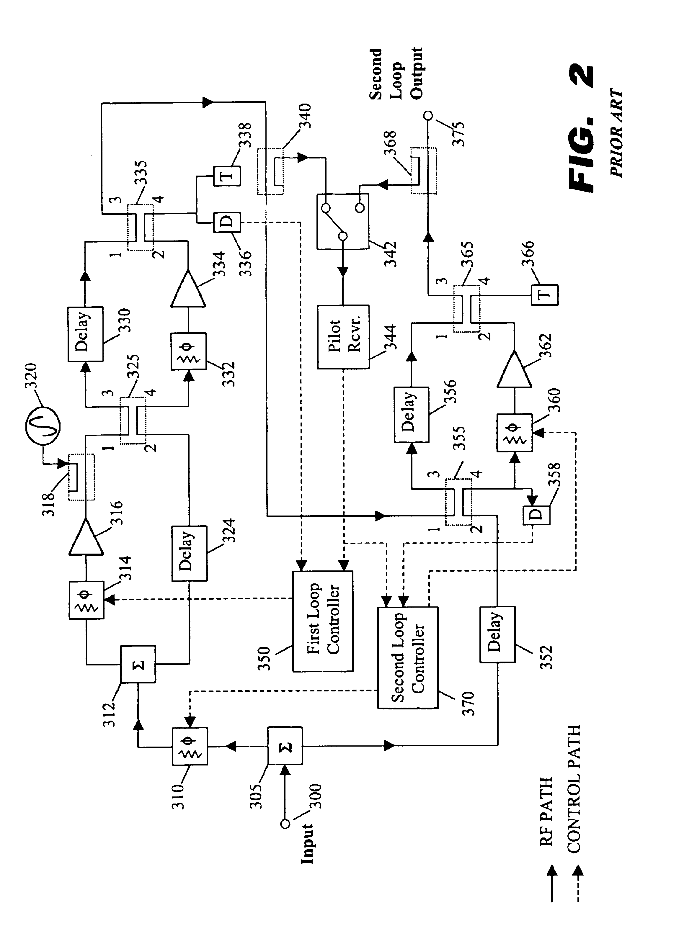
[0051]FIG. 3 is a block diagram of conventional dual loop feedforward power amplifier. FIG. 3 is the same as FIG. 1 except that a second feedforward power amplifier 111 replaces the main amplifier 110 of FIG. 1 which was shown as a single gain block, such as a simple cascade of one transistor amplifiers of fixed gain, that do not have feedback or feedforward control.

[0052]Thus, the first feedforward amplifier is embedded as a gain block in a second feedforward amplifier. Such an arrangement is typically called a dual loop feedforward amplifier (DLFFA). Those skilled in the art will appreciate that various embodiments...


PUM


Abstract

A feedforward amplifier. The present invention therefore provides a feedforward amplifier, comprising: a pilot reference generator that generates a pilot signal; a first carrier cancellation loop; a first error amplifier loop including a first error amplifier, wherein the pilot signal is utilized to provide gain stabilization in the first error amplifier a third loop; a second carrier cancellation loop that includes a first phase and amplitude adjuster in module and a second amplitude and phase adjuster disposed between module and module, wherein the pilot signal is utilized to control the adjustment of the second carrier cancellation loop.

Description

CROSS-REFERENCE TO RELATED APPLICATIONS[0001]This application is related to co-pending U.S. patent application Ser. No. 10 / 723,802, filed same date herewith, entitled “SYSTEM AND METHOD OF CARRIER REINJECTION IN A FEEDFORWARD AMPLIFIER,” by Rabinovich et al., and also related to co-pending U.S. patent application Ser. No. 10 / 723,094, filed same date herewith, entitled “A SYSTEM AND METHOD OF PILOT TONE REUSE IN A FEEDFORWARD AMPLIFIER,” by Rabinovich, et al., the contents of which are incorporated by reference herein.BACKGROUND OF THE INVENTION[0002]The present invention relates to electronic communication systems, and more particularly to systems in which multiple signals are simultaneously transmitted at varying power levels.[0003]In electronic communication systems, it is often necessary that groups of information signals be amplified and transmitted simultaneously. For example, a cellular radio base station transmitter typically transmits signals to many active receiving mobile ...

Claims


Application Information

Patent Timeline
Patent Type & Authority Patents(United States)
IPC IPC(8): H03F3/66H03F1/32
CPCH03F1/3223
Inventor RABINOVICH, ALEXGURVICH, MARKHE, JIANQUING
Owner INTEL CORP
Why Eureka
Try Eureka