
Multi-clad optical fiber lasers and their manufacture

a multi-clad optical fiber and laser technology, applied in the field of optical fibers, can solve the problems and achieve the effect of increasing the damage threshold of the fiber and the applicable maximum pump power

Active Publication Date: 2005-10-25
BIOLITEC UNTERNEHMENSBETEILLIGUNGS II AG +1
View PDF16 Cites 68 Cited by
  • Summary
  • Abstract
  • Description
  • Claims
  • Application Information

AI Technical Summary

Benefits of technology

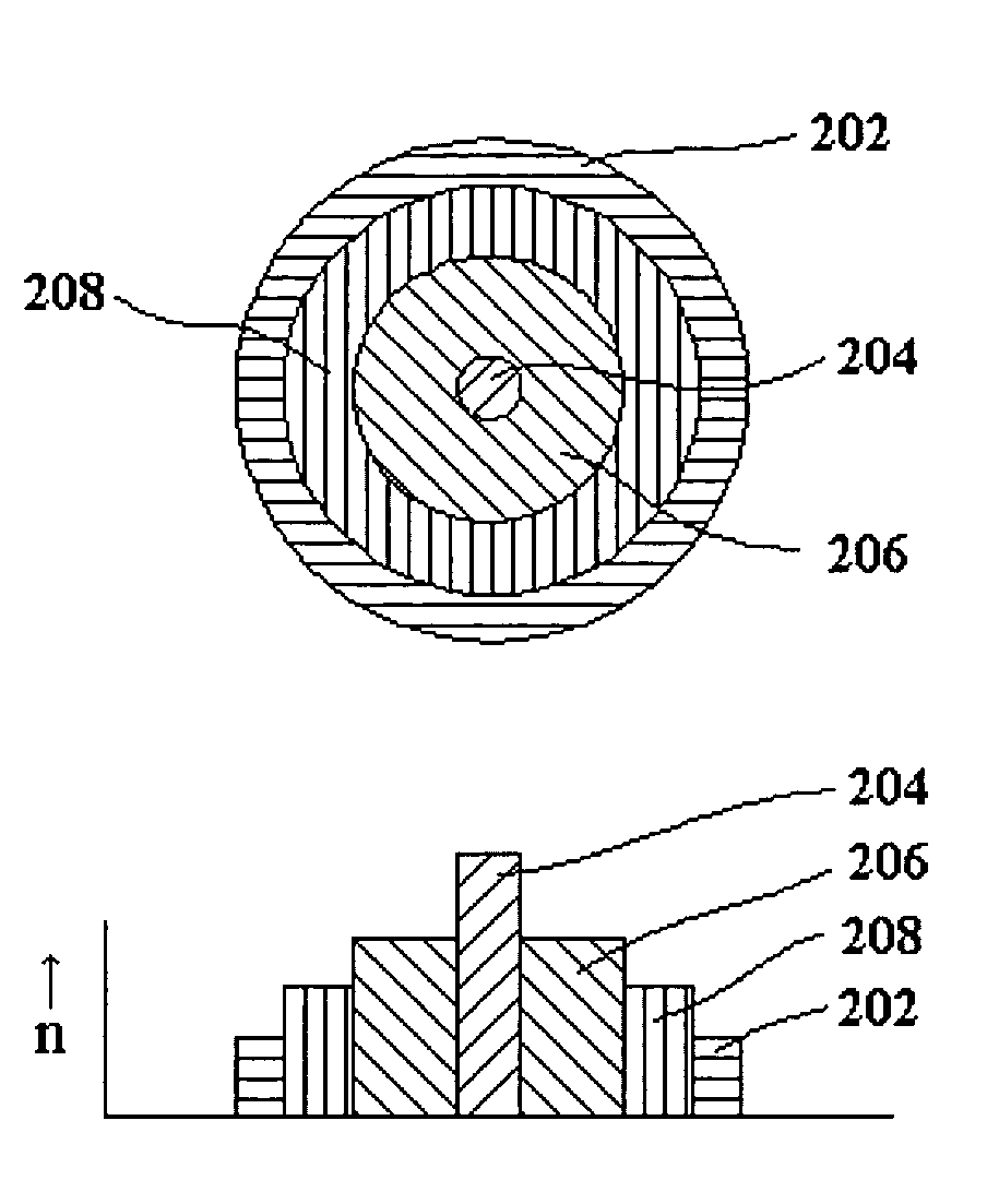
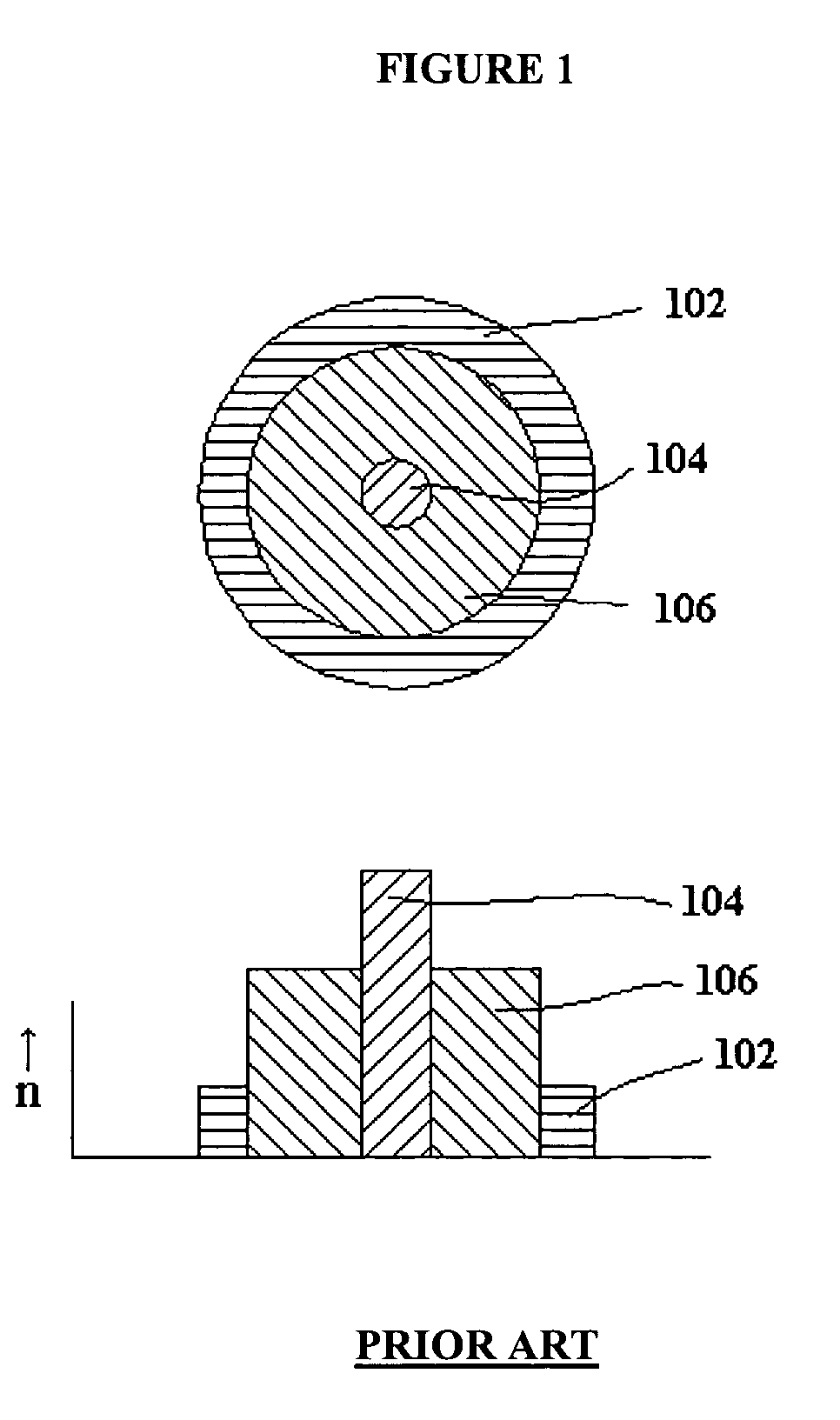
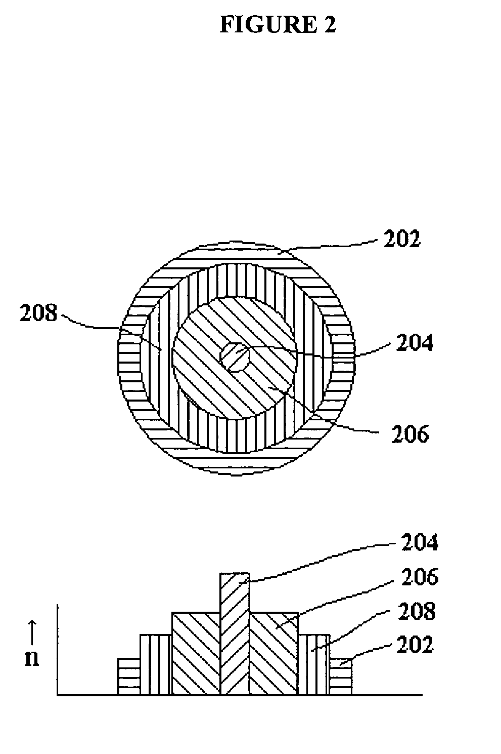
[0020]Briefly stated, the present invention discloses an optical fiber that can be used as an active medium in fiber lasers and / or fiber amplifiers, featuring a preferably rare earth-doped silica active core (also referred to as “fiber core”, “active core”, or “laser core”) surrounded by a pure or doped silica cladding layer (“pump core”). The active core is designed to provide high-power high-brightness laser radiation. The pump core is designed to allow for launching of appropriate high-power pump light, especially emission of high-power low-brightness pump sources such as laser diodes, laser-diode bars and / or laser-diode arrays. The pump core is surrounded by a doped or pure silica inner cladding for guiding pumping radiation within the pump core. Thus, the refractive index of the inner cladding is lower than that of the pump core. The fiber is surrounded by a protective coating made of, for example, polymeric material. One or more additional outer cladding layers, having refractive indexes lower than said inner cladding, may optionally be placed between the inner cladding and the protective coating to further protect the polymer coating from damage. Unlike the prior art, the protective coating does not serve as the only cladding, but is assisted by the inner cladding and optional outer cladding(s). The resultant fiber restricts radiation mainly to silica layers, thereby increasing the damage threshold of the fiber and the applicable maximum pump power that can be launched into the fiber.

Problems solved by technology

The resultant fiber restricts radiation mainly to silica layers, thereby increasing the damage threshold of the fiber and the applicable maximum pump power that can be launched into the fiber.

Method used


Image

  • Multi-clad optical fiber lasers and their manufacture
  • Multi-clad optical fiber lasers and their manufacture
  • Multi-clad optical fiber lasers and their manufacture

Examples


example 1

Circular Core Fiber Laser

[0059]A multi-clad fiber laser with a circular core structure consists of a low mode (near-single mode) laser-active core with a diameter of 12 μm and NA=0.16. The pump core diameter is equal to 400 μm, NA=0.24 with respect to the glass cladding and NA=0.36 with respect to the polymer coating. The glass cladding layer, deposited by PCVD, is 20 μm thick, and is surrounded by a silicone coating.

example 2

D-shaped Core Fiber Laser

[0060]A multi-clad fiber laser with a D-shaped core structure has the same characteristics as Example 1. However, in this case, approximately 10% of the pump core has been removed on one side to yield the D-shape prior to applying the material of the glass clad.

example 3

Doping Concentrations

[0061]Yb-doping: 0.6 mol % Yb2O3, co-doping: 4 mol % Al2O3 [0062]Nd-doping: 0.1 mol % Nd2O3, co-doping: 4 mol % Al2O3


PUM

PropertyMeasurementUnit
poweraaaaaaaaaa
powersaaaaaaaaaa
diameteraaaaaaaaaa

Abstract

An optical fiber is disclosed that can be used as an active medium in fiber lasers and / or fiber amplifiers, featuring a preferably rare-earth-doped silica active core surrounded by a pure or doped silica cladding layer (“pump core”). The pump core is surrounded by a doped or pure silica inner cladding for guiding pumping radiation within the pump core. Thus, the refractive index of the inner cladding is lower than that of the pump core. The fiber is surrounded by a protective coating made of polymeric material. One or more additional outer cladding layers, having refractive indexes lower than said inner cladding, may optionally be placed between the inner cladding and the protective coating to further protect the polymer coating from damage. Unlike the prior art, the protective coating does not serve as the only cladding, but is assisted by the inner cladding and optional outer cladding(s). The resultant fiber restricts radiation mainly to silica layers, thereby increasing the damage threshold and the applicable maximum pump power of the fiber.

Description

DOMESTIC PRIORITY UNDER 35 USC 119(e)[0001]This application claims the benefit of U.S. Provisional Application Ser. No. 60 / 442,715, filed Jan. 27, 2003, which is incorporated by reference herein.BACKGROUND OF THE INVENTION[0002]1. Field of the Invention[0003]The present invention relates to the field of optical fibers for the generation and / or amplification and transmission of high power laser energy.[0004]2. Information Disclosure Statement[0005]Many applications require or benefit from the use of a high-power pump-light source. Use of a conventional laser-active single mode fiber is insufficient to launch high-power pump radiation in order to achieve high-power laser emission. There are numerous techniques available for increasing a fiber's output power, such as attempts to reduce energy density at fiber end faces through devices such as tapered fiber tips. Another common technique to overcome this obstacle is the use of appropriate so-called double-clad fibers. The use of a doubl...

Claims


Application Information

Patent Timeline
Patent Type & Authority Patents(United States)
IPC IPC(8): G02B1/00H01S3/30C03B37/014C03B37/018C03C13/04C03C25/10G02BG02B6/02H01S3/067
CPCC03B37/01426C03B37/01807C03C13/046C03C25/104H01S3/06708C03B2203/12C03B2203/23H01S3/06729
Inventor SANDROCK, THOMASUNGER, SONJAHARSCHACK, ALEXANDERREICHEL, VOLKER
Owner BIOLITEC UNTERNEHMENSBETEILLIGUNGS II AG
Learn More