Compression mount and zero insertion force socket for IC devices

a technology of compression mount and socket, which is applied in the direction of coupling device connection, electrical apparatus construction details, instruments, etc., can solve the problems of ic device b>106/b> being clamped to the socket, causing compression force on the pins, and deleterious to the ic device, so as to prevent the warping of the circuit board and minimize the electrical path length

Inactive Publication Date: 2005-11-01
ADVANCED MICRO DEVICES INC
View PDF11 Cites 21 Cited by
  • Summary
  • Abstract
  • Description
  • Claims
  • Application Information

AI Technical Summary

Benefits of technology

[0015]In a further embodiment of the present invention, a back plate is mounted to a back-side of the circuit board when the socket is mounted to a front-side of the circuit board, for preventing warping of the circuit board.
[0016]In this manner, with use of the zif opening, substantially zero force is applied on the body of the IC device that is not clamped to the socket in an embodiment of the present invention. Rather, the pin of the IC device is compressed between the forking leads within the zif opening to be coupled to the contact pad of the circuit board. In addition, the forking leads make electrical contact with the top portion of the pin toward the IC device to minimize the electrical path length between the IC device and the contact pad of the circuit board.

Problems solved by technology

Referring to FIGS. 2 and 4, one disadvantage of the prior art socket system 100 is that the body of the IC device 106 is clamped to the socket 102.
Such clamping force and the compression force on the pins 104 may be deleterious to the IC device 106.
Such forces may warp and damage the structures of the IC device 106 which may lead to malfunction of the IC device 106.

Method used


Image

  • Compression mount and zero insertion force socket for IC devices
  • Compression mount and zero insertion force socket for IC devices
  • Compression mount and zero insertion force socket for IC devices

Examples


Embodiment Construction

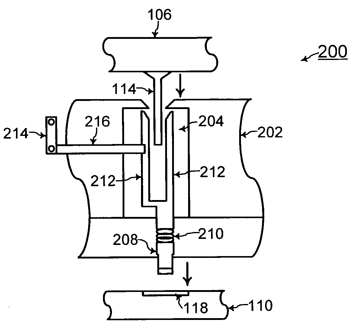
[0029]Referring to FIGS. 5 and 8, a socket system 200 includes a socket 202 for coupling the pins 104 of the IC device 106 to the contact pads 108 of the circuit board 110, according to an embodiment of the present invention. The mechanism within one zif (zero-insertion-force) opening 204 of the socket 202 is illustrated in FIG. 5 for simplicity and clarity of illustration and description. However, the socket 202 includes a plurality of such zif openings with each zif opening coupling a respective one of the pins 104 of the IC device 106 to a respective one of the contact pads 108. FIG. 5 illustrates one example zif opening 204 for coupling an example pin 114 of the IC device 106 to an example contact pad 118 of the circuit board 110.

[0030]Referring to FIGS. 6 and 8, the socket 202 is mounted to the circuit board 110 with a screw mechanism 206 according to one embodiment of the present invention. Screw mechanisms are known to one of ordinary one of skill in the art of mechanics, and...


PUM


Abstract

In a socket system and method for coupling a pin of an IC (integrated circuit) device to a contact pad of a circuit board, a zif opening on a socket asserts substantially zero force as the pin of the IC device is inserted therein. In addition, a compression mount lead on the socket presses against the contact pad of the circuit board. Once inside the zif opening, the pin is coupled to the compression mount lead via forking leads that press against the pin. Thus, substantially zero force is applied on the body of the IC device. Furthermore, top portions of the forking leads contact a top portion of the pin toward the IC device to minimize an electrical path length.

Description

TECHNICAL FIELD[0001]The present invention relates generally to integrated circuit technology, and more particularly, to a socket system and method using zero insertion force and compression mount for holding an IC (integrated circuit) device to a circuit board.BACKGROUND OF THE INVENTION[0002]Referring to FIG. 1, a socket system 100 of the prior art includes a socket 102 for coupling a plurality of pins 104 of an IC (integrated circuit) device 106 to a corresponding plurality of contact pads 108 of a circuit board 110. The pins 104 of the IC device may be arranged as an array when the IC device is implemented as a micro-pin grid array IC package, as known to one of ordinary skill in the art of integrated circuits. Each of the pins 104 of the IC device 106 is coupled to a respective one of the contact pads 108 via a respective one of the leads 112 of the socket 102. For example, a first pin 114 of the IC device 106 is coupled via a first lead 116 of the socket 102 to a first contact...

Claims


Application Information

Patent Timeline
Patent Type & Authority Patents(United States)
IPC IPC(8): G01R1/04G01R1/02H05K7/10H01R12/71
CPCG01R1/0466H05K7/1007H05K7/1084H01R12/714H01R12/89H01R12/71H01R33/76
Inventor HUSSAIN, RAFIQCYMERYS, JEFFREY
Owner ADVANCED MICRO DEVICES INC
Why Eureka
Try Eureka