
Intravascular stent device

a stent and vascular technology, applied in the field of stent devices, can solve the problems of extremely small valves and tortuous throughout their length, and achieve the effect of improving the vascular permeability and vascular permeability

Inactive Publication Date: 2005-11-01
CODMAN & SHURTLEFF INC
View PDF92 Cites 64 Cited by
  • Summary
  • Abstract
  • Description
  • Claims
  • Application Information

AI Technical Summary

Benefits of technology

Enables effective deployment and repositioning of the stent within small and tortuous vessels while maintaining structural integrity, allowing for improved blood flow and obstruction of aneurysms, with the ability to deliver embolic coils and prevent their escape.

Problems solved by technology

Obviously, such vessels are extremely small and very tortuous throughout their length.

Method used


Image

  • Intravascular stent device
  • Intravascular stent device
  • Intravascular stent device

Examples


Embodiment Construction

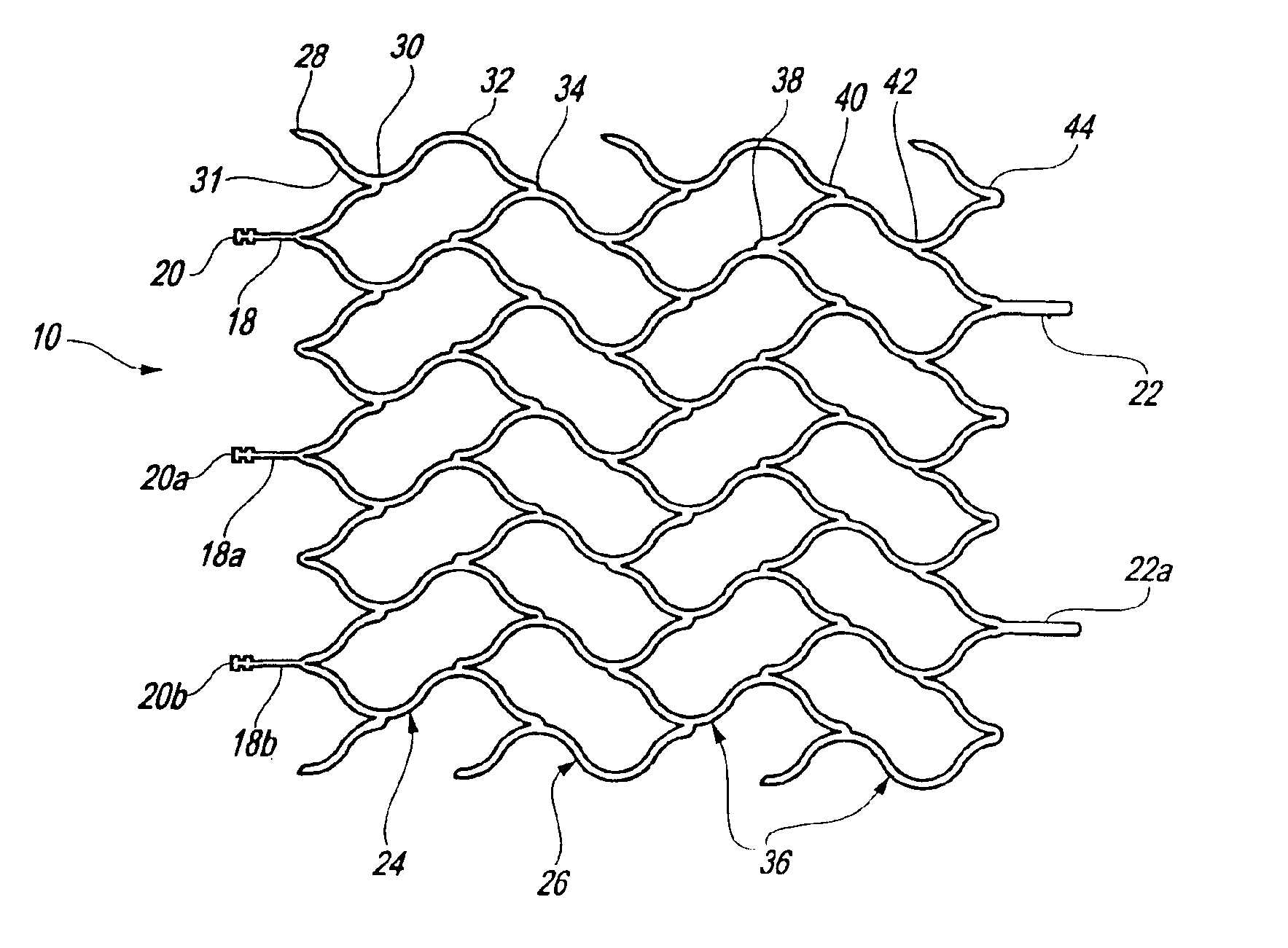
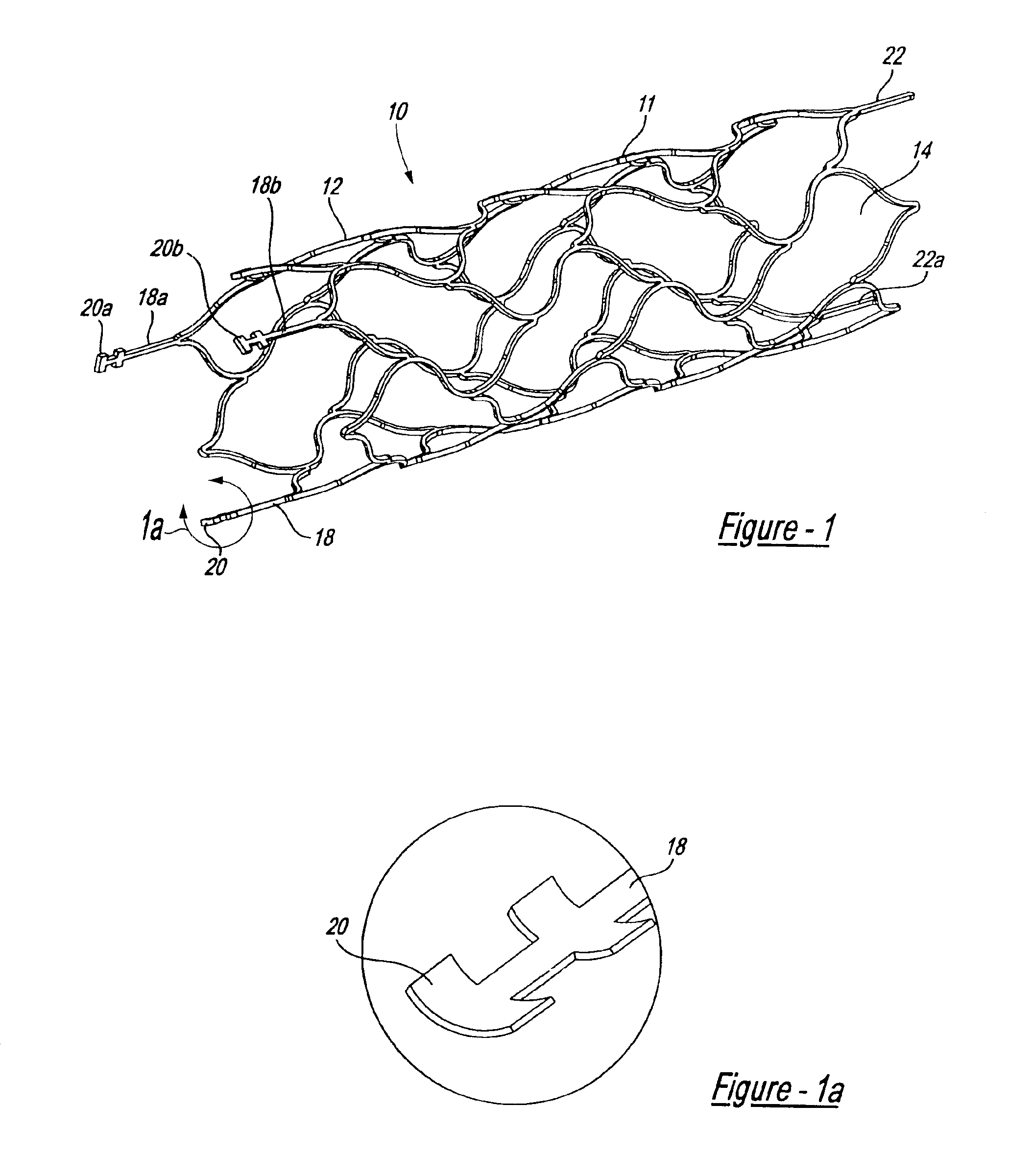
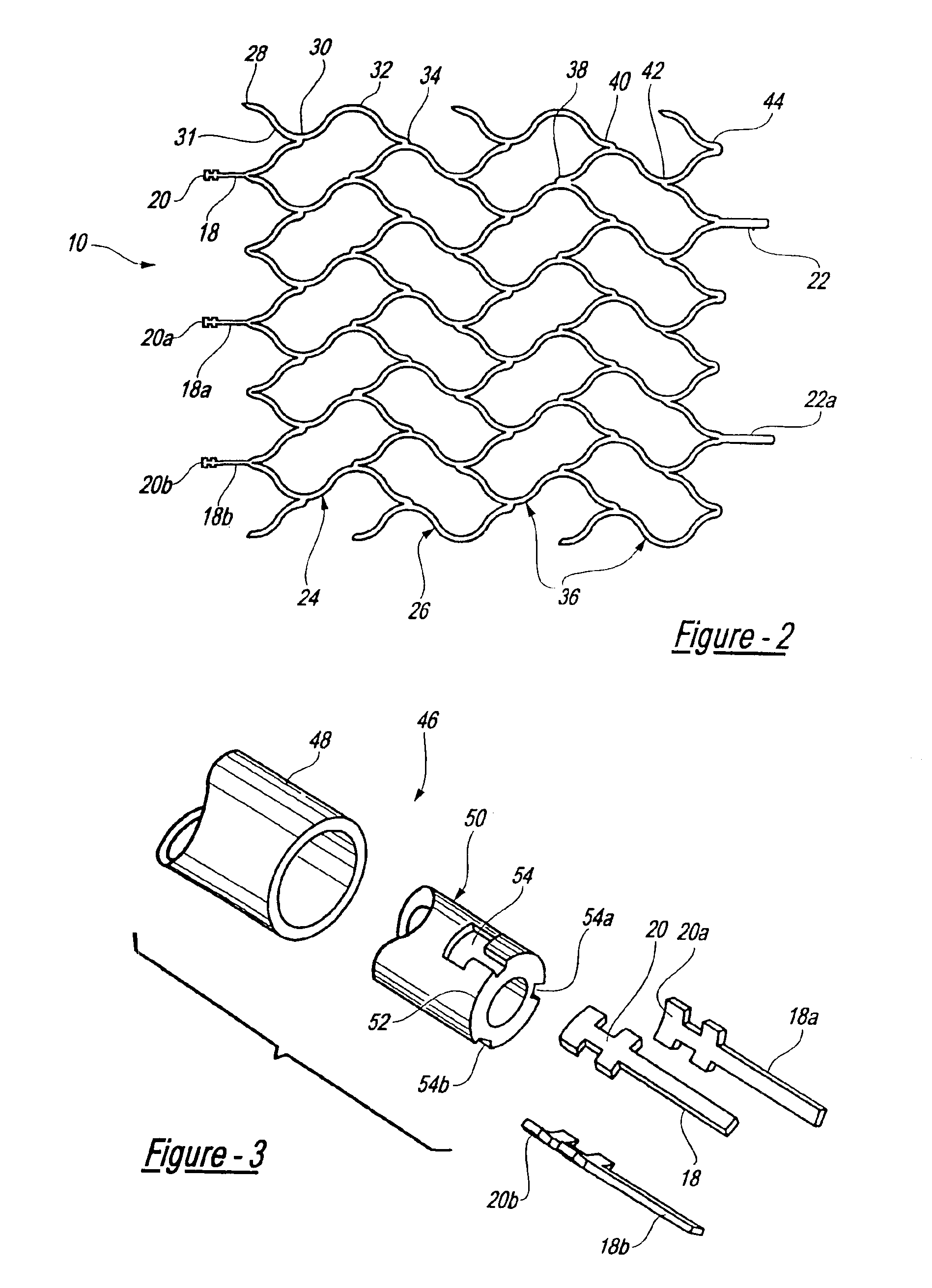
[0025]FIG. 1 illustrates a self-expanding stent device 10 which is laser cut to form a thin-walled, skeletal tubular member 11 comprised of nickel-titanium alloy. Once cut, the wall 12 of the tubular member 11 includes several openings, or cells 14. When the skeletal tubular member 11 is placed over an aneurysm, a physician is able to deliver embolic coils or other such devices through the cells 14 and into the aneurysm. The tubular member 11 also functions to cover the mouth of the aneurysm thus obstructing, or partially obstructing, the flow of blood into the aneurysm. Also, the tubular member 11 prevents medical devices such as embolic coils from escaping the aneurysm.

[0026]The preferred length of the skeletal tubular member 11 may range from 0.0795 inches to 3.15 inches. The diameter of the tubular member 11 varies depending on its deployment configuration. In a non-deployed or expanded state, the diameter of the tubular member 11 may extend up to about 0.4 inches. When the skel...


PUM


Abstract

A very small diameter intravascular stent device which may be used to occlude or partially occlude an aneurysm in the human brain, the stent device includes a thin-walled skeletal cylindrical tube fonned of S-shaped, or sinusoidal, elements which, when compressed, nest tightly with each other.

Description

CROSS-REFERENCE TO RELATED APPLICATION[0001]This patent application is a divisional patent application of U.S. patent application Ser. No. 10 / 163,116, filed on Jun. 5, 2002, entitled, “Intravascular Stent Device,” now U.S. Pat. No. 6,673,106, which is a nonprovisional patent application of U.S. provisional patent application Ser. No. 60 / 298,326, filed on Jun. 14, 2001, entitled, “Intravascular Stent.”BACKGROUND OF THE INVENTION[0002]1. Field of the Invention[0003]This invention relates to intravascular devices for implantation within a vessel of the body, and more particularly to a stent device which may be used in the treatment of blood vessel disorders. More specifically, the intravascular device may take the form of an aneurysm cover to be used in the treatment of aneurysms which occur in the brain.[0004]2. Description of the Prior Art[0005]On a worldwide basis, nearly one million balloon angioplasties were performed in 1997 to treat vascular disease, including blood vessels clog...

Claims


Application Information

Patent Timeline
Patent Type & Authority Patents(United States)
IPC IPC(8): A61F2/06A61F2/90A61F2/84
CPCA61F2/91A61F2/915A61F2002/91533A61F2002/9155A61F2002/91558A61F2002/91591A61F2002/9665A61F2230/0013
Inventor MITELBERG, VLADIMIRJONES, DONALD K.
Owner CODMAN & SHURTLEFF INC
Learn More