Optical disk producing device and producing method

Inactive Publication Date: 2005-11-01
ORIGIN ELECTRIC CO LTD
View PDF12 Cites 3 Cited by
  • Summary
  • Abstract
  • Description
  • Claims
  • Application Information

AI Technical Summary

Benefits of technology

[0021]According to the invention defined in claim 16, there is provided an optical disc manufacturing method for manufacturing an optical disc constituted by two sheets of mutually adhered disc substrates, comprising: a film forming step for forming reflective films sequentially or alternately on the sequentially supplied disc substrates; a reversing step for reversing one of a pair of the disc substrates; a step for supplying the liquid adhesive on an upper surface of each of the disc substrates which is not reversed at the reversing step or a lower surface of each of the disc substrates

Problems solved by technology

Furthermore, the recording capacity of the optical disc is tended to be more highly dense.
However, a considerable heat is used to soften a resin material during the molding.
Consequently, this mechanism becomes large sized and there is a possibility of adhering a dust on an upper surface of the disc substrates.
However, since a distance by which the two sheets of optical disc substrates are moved becomes long and there is a high possibility of adhering a dust on the upper surfaces of the disc substrates.
In addition, an occupied area of the dust cann

Method used


Image

  • Optical disk producing device and producing method
  • Optical disk producing device and producing method
  • Optical disk producing device and producing method

Examples


Embodiment Construction

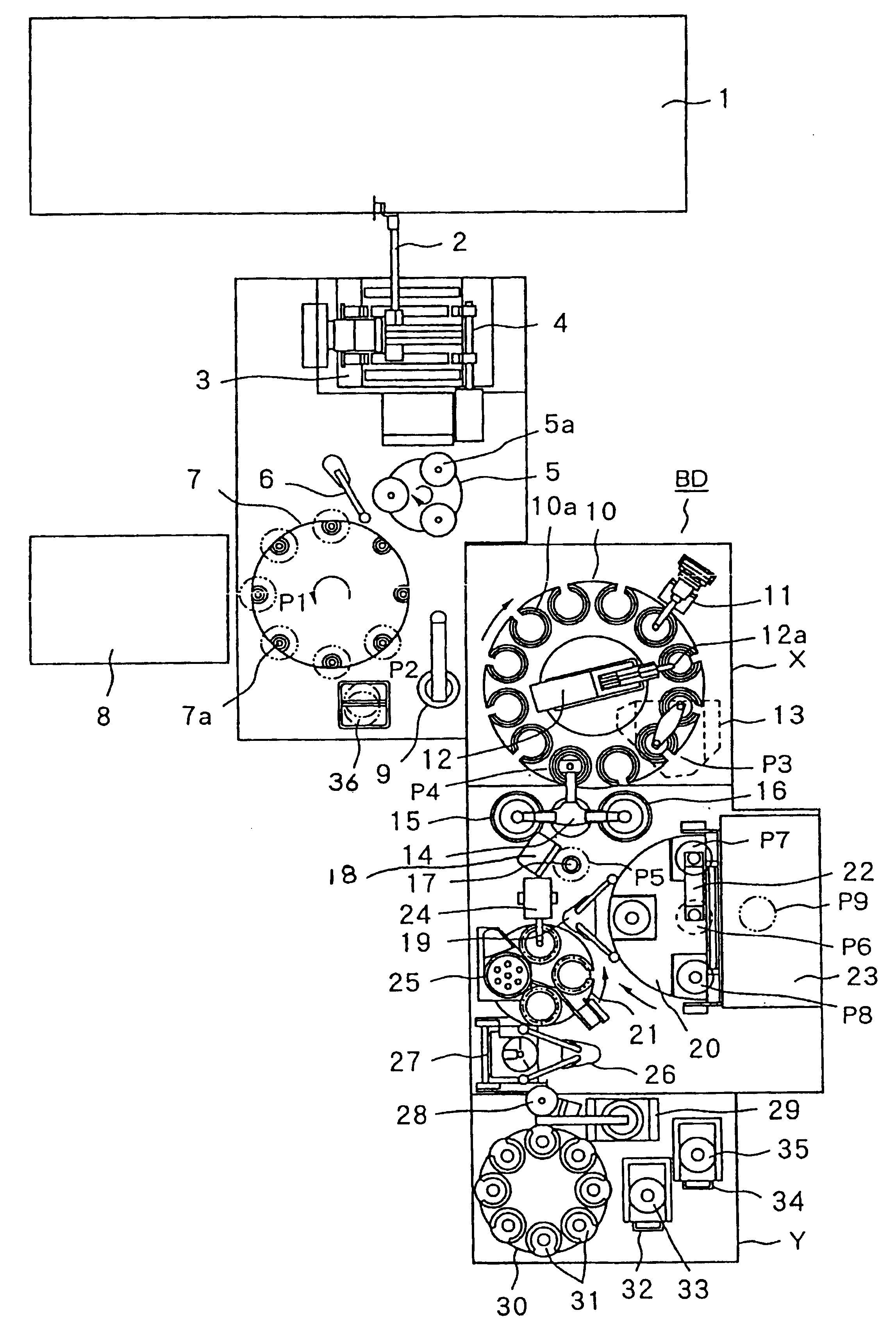
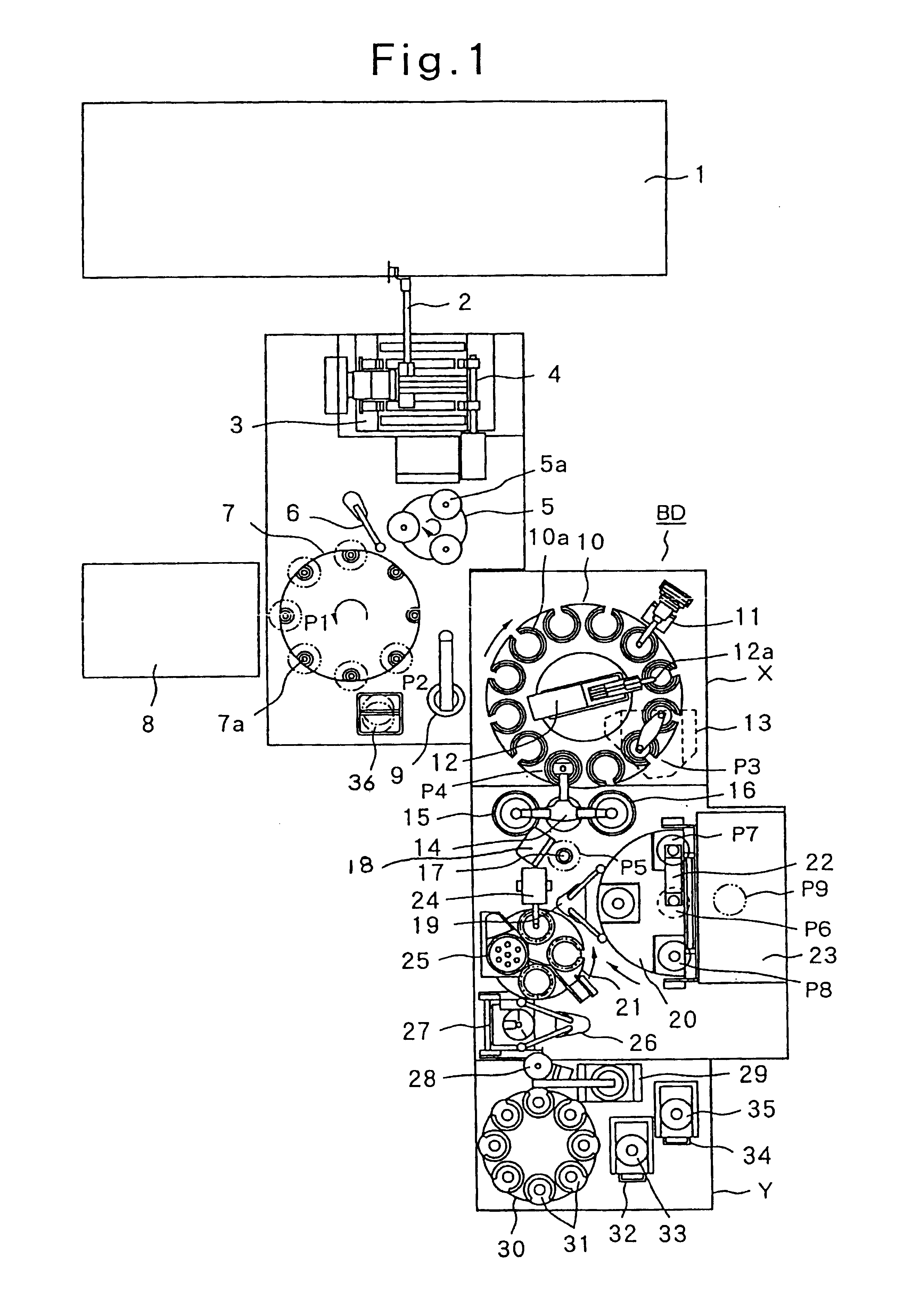
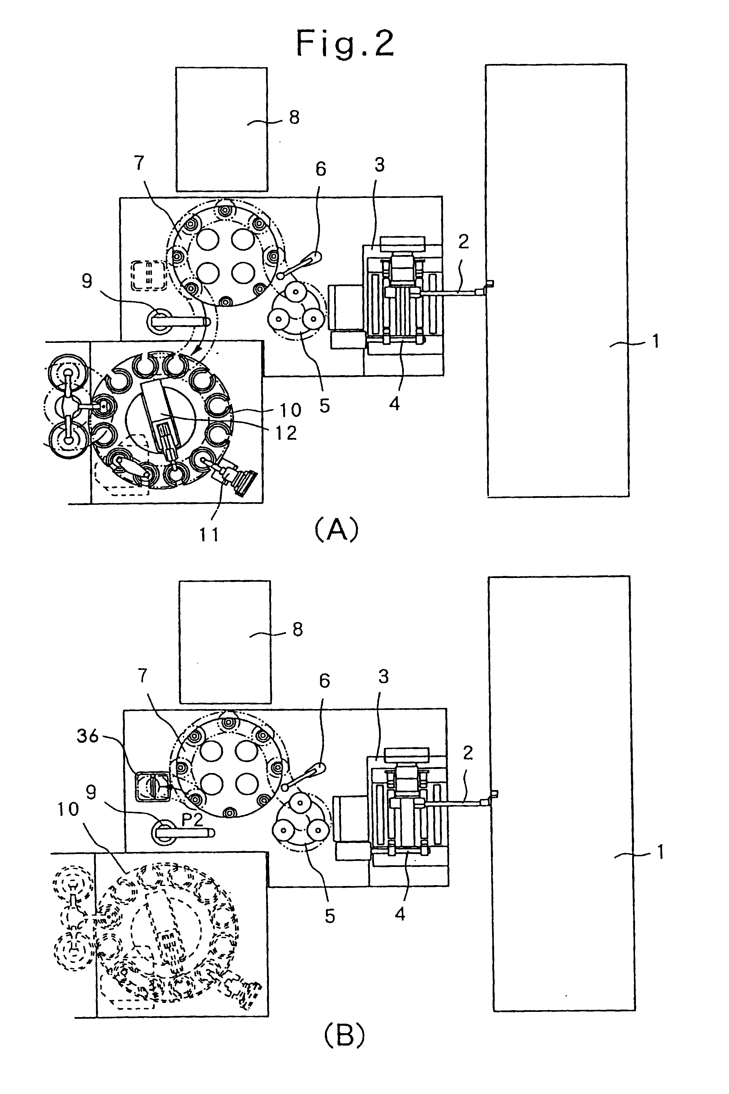
[0033]First, a preferred embodiment of an optical disc manufacturing apparatus according to the present invention which corresponds to that of an optical disc manufacturing method according to the present invention will be described with reference to FIG. 1 which shows a rough configuration of the optical disc manufacturing apparatus.

[0034]In FIG. 1, reference numeral 1 denotes a molding machine which can simultaneously mold two sheets of disc substrates on each of respective surfaces of which a different information is recorded.

[0035]A transfer mechanism 2 serving as movably mounting means includes a movably mounting arm and its drive unit. Movably mounting means 2 absorbs, holds, and receives simultaneously two sheets of disc substrates carried from molding machine 1, turns in a substantially vertical direction, and mounts them onto a cooling mechanism 3 which will be described in details later.

[0036]Cooling mechanism 3 is used to cool each of the disc substrates which has finishe...


PUM

PropertyMeasurementUnit
Angleaaaaaaaaaa
Fractionaaaaaaaaaa
Timeaaaaaaaaaa

Abstract

A molding machine 1 which molds two sheets of disc substrates on which the information is recorded simultaneously, a cooling mechanism 3 for cooling each of the disc substrates, first movably mounting means 2 for movably mounting the disc substrate from the molding machine onto the cooling mechanism, and a second movably mounting means 4 for mounting each of the disc substrates onto a receiving portion of the turn table 5 are provided. In addition, a film forming device 8 for receiving sequentially each of the disc substrates from this movably mounting means 6 and forming a reflective film on one of the surfaces of each of the received disc substrates on which the information is recorded; a turn table 10 having a plurality of receiving portions on which the disc substrates are mounted and which rotates intermittently through each constant angle; a reversing mechanism 11 which reverses 180 degrees each of the disc substrates; and an overlapping mechanism for overlapping the reversed disc substrates over the other disc substrates are provided. Furthermore, spinners 15, 16 for rotating the overlapped two sheets of disc substrates and a curing device 23 which radiates ultra-violet rays onto the disc substrates which are rotated by the spinners to cure the liquid adhesive. According to the above-described structure, an optical disc which is compact, is fast in a production speed, and has a high quality can be achieved.

Description

TECHNICAL FIELD[0001]The present invention relates to techniques of manufacturing an optical disc which is capable of reading optically a recorded information and of adhering two sheets of optical disc substrates.BACKGROUND ART[0002]A technology of increasing a record capacity through an optical disc has been developed and has widely been spread. Furthermore, the recording capacity of the optical disc is tended to be more highly dense. For example, an optical disc having a recording capacity of 8.5 gigabytes called DVD-9 and recorded from both surfaces for each layer in a double layer structure has been produced. A manufacturing method of such a kind of optical disc as described above is such that two sheets of disc substrates are formed on which mutually different information is recorded by means of two molding machines and reflective films having different reflectivities are formed on their corresponding recording surfaces by means of two sputtering devices and disc substrates are...

Claims


Application Information

Patent Timeline
IPC IPC(8): G11B7/26B29C65/48
CPCG11B7/265Y10T156/1744G11B7/24027G11B7/24024
Inventor MATSUMOTO, YUTAKANISHIMURA, HIRONOBUKOTOYORI, MASAHIKOYAMAGUCHI, KOJINAITO, YOSHIHIKO
Owner ORIGIN ELECTRIC CO LTD
Why Eureka
Try Eureka