Centrifugal turbine for breathing-aid devices

Inactive Publication Date: 2005-11-01
COVIDIEN AG
View PDF8 Cites 178 Cited by
  • Summary
  • Abstract
  • Description
  • Claims
  • Application Information

AI Technical Summary

Benefits of technology

[0014]The aim of the invention is to overcome these drawbacks of the prior art by providing a more compa

Problems solved by technology

Patients suffering from these disorders are liable, during their sleeping time, to pass through phases of apnoea during which they stop breathing, thus causing them to wake up.
These devices of the prior art have a drawback as r

Method used


Image

  • Centrifugal turbine for breathing-aid devices
  • Centrifugal turbine for breathing-aid devices
  • Centrifugal turbine for breathing-aid devices

Examples


Example

[0034]In the following description, the terms upper, lower, above, below, vertical and horizontal refer to the turbine in the position in which it is depicted in FIGS. 1 to 3.

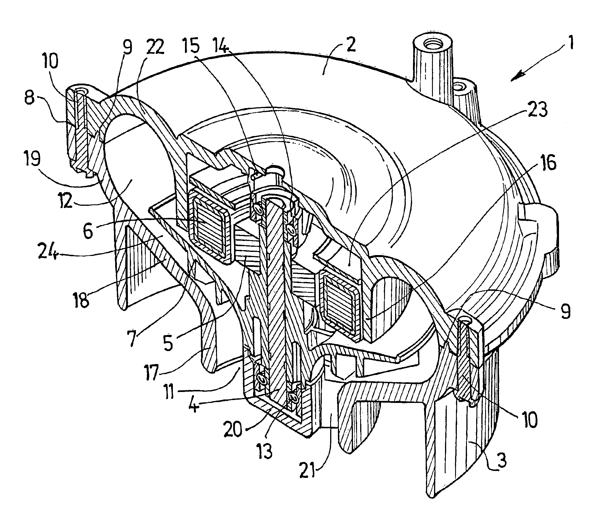
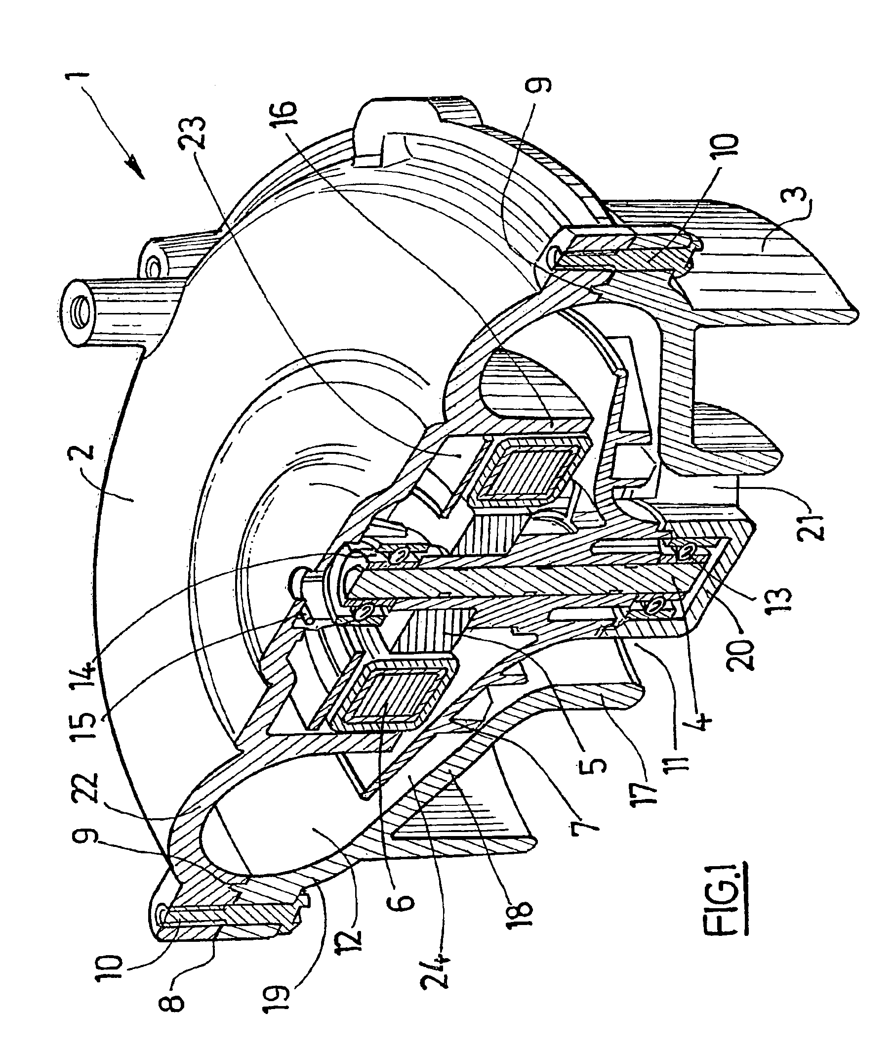
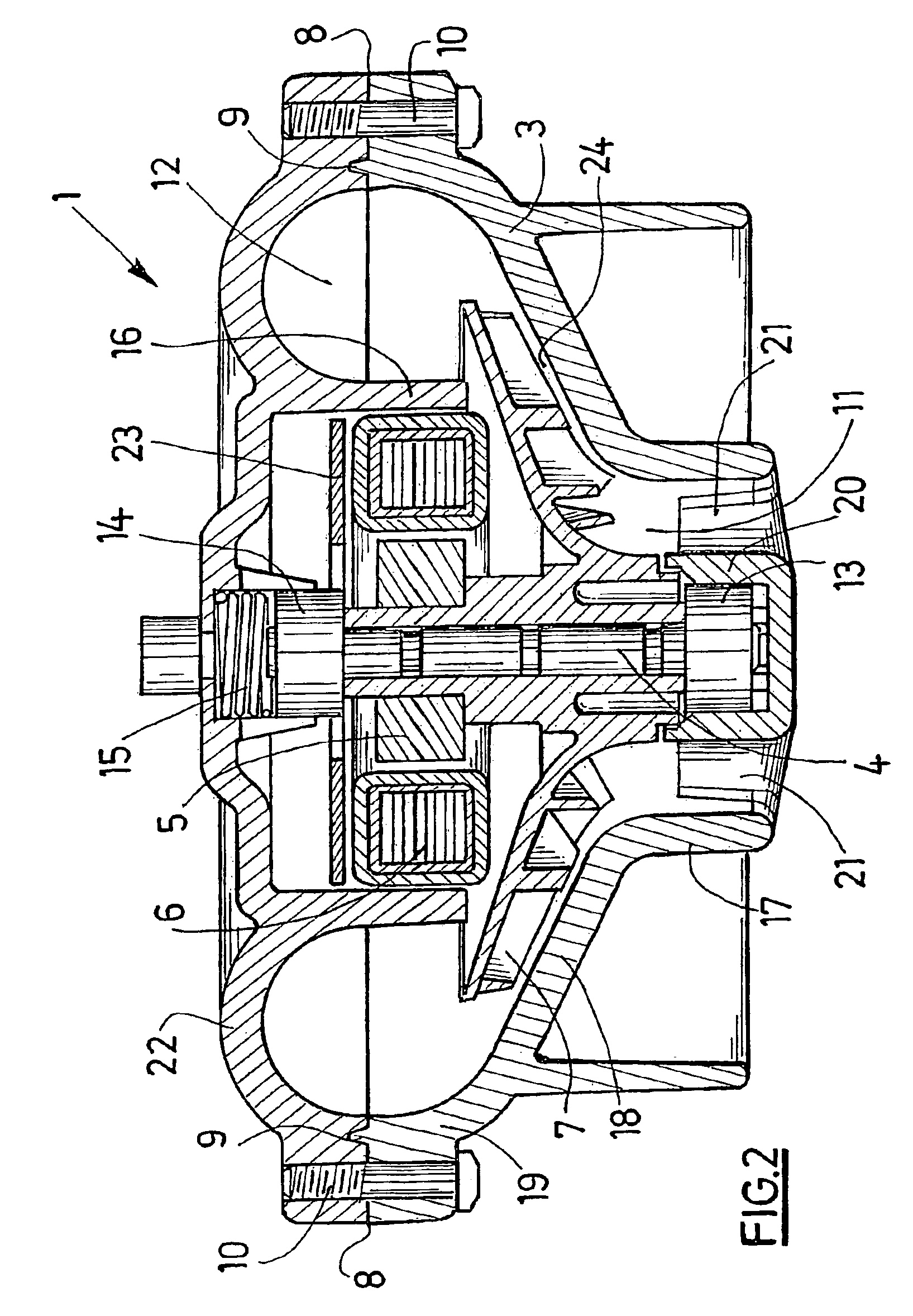
[0035]The turbine 1 depicted in FIGS. 1, 2 and 3 comprises an upper body 2 assembled with a lower body 3, defining between them a volume in which there are positioned a vertical shaft 4 mounted on two roller bearings 13, 14, a toric magnet 5, a toric coil 6 and a blade-carrying wheel 7.

[0036]The upper body 2 is dish-shaped, comprising an internal annular skirt 16 (on the side of the lower body 3) coaxial with said dish and intended to form a motor housing, and a semi-toric wall 22 situated on the periphery of the dish.

[0037]The lower body 3 has a hollow shape delimited by a first annular wall 17 connected to a second conical wall 18 widening out towards the top and itself connected to a connecting wall 19 with an arc of a circle cross-section.

[0038]The annular wall 17 surrounds a hub 20 intended for mounting th...


PUM


Abstract

The invention concerns an electric turbin (1) comprising a turbine rotor (4, 7), a turbine stator (2, 3), an electric motor member (5, 6) for driving the rotor (4, 7) in rotation relative to the stator (2, 3), and having the following features: the turbine stator (2, 3) comprises a stator body defining a compression chamber (12); the turbine rotor (4, 7) includes a plurality of blades (26, 27) integral with a shaft (4) mounted coaxially rotating in the body (2, 3) of the turbine stator; the electric motor member (5, 6) comprises a toroidal motor stator (6) housed in a motor housing (16, 23) of the turbine stator (2, 3), at the center of the toroidal compression chamber (12) and a motor rotor (5) mounted on the shaft (4) of the turbine rotor, axially opposite the motor stator (6).

Description

RELATED APPLICATIONS[0001]This is a U.S. national phase of PCT / FR02 / 03846 filed Nov. 8, 2002, claiming priority from FR 01 / 15314 filed Nov. 27, 2001.BACKGROUND OF THE INVENTION[0002]The invention concerns motorised turbines intended for the production of a continuous flow of air and more particularly the turbines equipping respiratory assistance devices.[0003]These respiratory assistance devices can be provided for treating sleep apnoea disorders.[0004]Patients suffering from these disorders are liable, during their sleeping time, to pass through phases of apnoea during which they stop breathing, thus causing them to wake up.[0005]To remedy these disorders, there exist devices comprising a respiratory mask applied over the nose and / or mouth of a user while he is asleep, and a case supplying pressurised air to this mask so as to prevent the user entering an apnoea phase.[0006]In order to supply the pressurised air to the respiratory mask, the known respiratory assistance devices gene...

Claims


Application Information

Patent Timeline
IPC IPC(8): F04D25/02F04D17/00F04D25/06F04D17/06F04D29/30F04D29/00A61M16/00F04D17/10F04D25/08F04D29/28
CPCF04D17/06F04D25/0606F04D29/30F04D29/281
Inventor NADJAFIZADEH, HOSSEINPERINE, PHILIPPELIEGEOIS, PASCAL
Owner COVIDIEN AG
Why Eureka
Try Eureka