Forward link repeater frequency watermarking scheme

a repeater frequency and forward link technology, applied in the field of position location systems, can solve the problems of not being able to obtain enough gps measurements to determine the location of the receiver, not being able to accurately locate the gps receiver, and only limited success of aflt (including a-gps) for position location purposes, so as to reduce the time to fix

Active Publication Date: 2005-11-01
QUALCOMM INC
View PDF6 Cites 42 Cited by
  • Summary
  • Abstract
  • Description
  • Claims
  • Application Information

AI Technical Summary

Benefits of technology

[0022]In some embodiments, where A-GPS is used to determine position location, a GPS search is performed prior to performing the repeater AFLT search. If sufficient GPS measurements for position location determination are obtained, the repeater AFLT search may be skipped in the interest of reducing time-to-fix.

Problems solved by technology

One problem with GPS-based position location determination arises if only three (or less) satellites can be found, and in such an instance (and in the absence of other ancillary information) it is not possible to accurately locate the GPS receiver.
For example, if the GPS receiver's view of the sky is obstructed (e.g., deep inside a concrete building) it may not be possible to obtain enough GPS measurements to determine receiver location.
In practice, AFLT (including A-GPS) has proven to be of only limited success for position location purposes, in part because repeaters employed in wireless networks cause an ambiguity as to the point of transmission of the pilot signal.
Because the point of transmission of the pilot signal is unknown (e.g., whether directly from a donor BTS or through a repeater), the AFLT measurement cannot be used to accurately determine position.
In addition, the repeater will also have internal delays, typically in a range from hundreds of nanoseconds up to tens of microseconds, potentially resulting in a position location error in the range of about 24.4 meters (for 100 nanoseconds) to about 2.44 kilometers (for 10 microseconds).
However, this solution completely precludes AFLT position location and any AFLT portion of A-GPS from being utilized in many locations, thus reducing position location availability and yield, and increasing GPS search windows, resulting in longer times-to-fix.
Unfortunately, the RL signature is expected to be of only limited assistance in mitigating the effects of repeaters on position location, because the mobile station uses AFLT measurements from the forward link for position location.
Introducing a signature onto the FL signal has also been suggested, such as described in U.S. Pat. No. 6,501,955, however no practical solution has yet been developed.

Method used


Image

  • Forward link repeater frequency watermarking scheme
  • Forward link repeater frequency watermarking scheme
  • Forward link repeater frequency watermarking scheme

Examples


example implementation

of FLRFWM

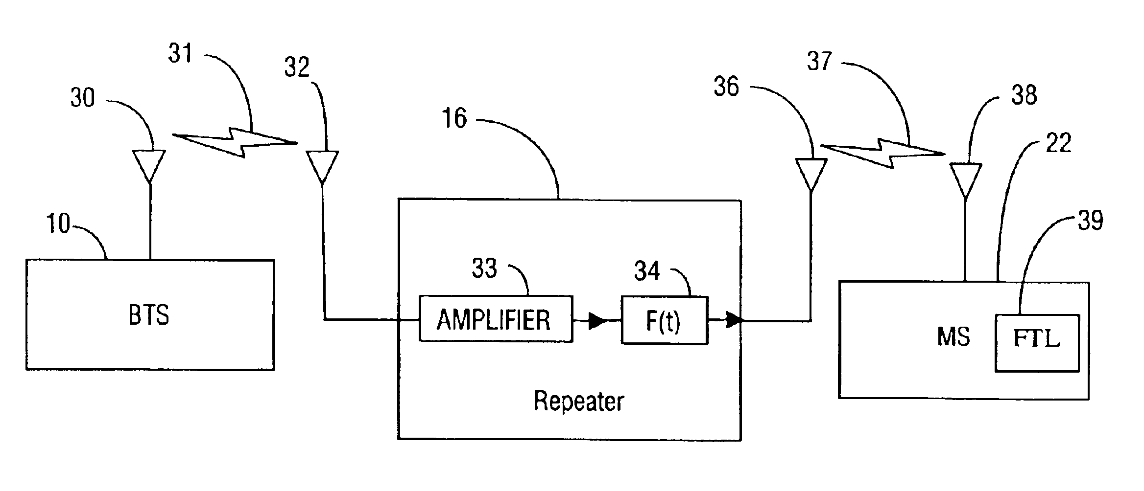
[0182]In one example embodiment, the FLRFWM is applied to a CDMA system to optimize position location performance. The results of the example implementation, for reasonable target error event probabilities, such as false alarm probability (PFA), probability of missed detection (PMISSDET), and probability of missed identification (PMISSID) of about 10−2, include identification of a FL frequency watermark for pilots down to about −16.9 dB in about 358 microseconds (ms), −19.2 dB in about 712 ms, −21.2 dB in about 1.423 sec, and −23.1 dB in about 2.844 sec.

[0183]In this example implementation, the modulation waveform applied to the forward link signal by the FM modulator is a periodic square wave of magnitude + / −fA and period of 2T, where fA in this example implementation is 50 Hz, and T is in [10*64: inc:11*64] chip range. It should be noted that the increment inc is chosen to achieve uniform spacing of watermarks in frequency for easier detection, and the value is then trunc...


PUM


Abstract

A forward link repeater frequency watermarking (FLRFWM) system and method that enable accurate position location of mobile stations in areas where repeaters are present by watermarking repeated signals with repeater information. A repeater watermarks a forward link signal with a (unique or non-unique) fast frequency modulation waveform watermark every time a signal passes through the repeater. A mobile station detects and/or identifies the fast frequency watermark on the forward link signal to determine repeater information that aids the network position determination entity or mobile station position location system in determining position location using AFLT and/or A-GPS systems. A forward link fast frequency watermarking system described herein achieves minimal impact on FL, AFLT, and GPS performance, good detection, identification and false alarm probabilities, short time-to-detect/identify, and good detection/identification sensitivity.

Description

CROSS-REFERENCE TO RELATED APPLICATION[0001]Priority is hereby claimed to U.S. Provisional Application No. 60 / 449,774, filed Feb. 24, 2003, entitled FORWARD LINK REPEATER FREQUENCY WATERMARKING SCHEME.BACKGROUND OF THE INVENTION[0002]1. Field of the Invention[0003]This invention relates to position location systems that utilize wireless signals to determine the location of an electronic mobile device.[0004]2. Description of Related Art[0005]Existing position location technologies based on GPS use a network of satellites in earth orbit that transmit signals at a known time. A GPS receiver on the ground measures the time-of-arrival of the signals from each satellite in the sky that it can “see”. The time-of-arrival of the signal along with the exact location of the satellites and the exact time the signal was transmitted from each satellite is used to triangulate the position of the GPS receiver. A GPS receiver requires four satellites to make a triangulation and the performance of th...

Claims


Application Information

Patent Timeline
Patent Type & Authority Patents(United States)
IPC IPC(8): G01S1/00G01S5/02G01S5/14H04B7/26H04Q7/38G01S19/06G01S19/25
CPCG01S5/0226G01S19/46H04B7/155H04B7/2606G01S5/0273G01S19/256G01S19/258
Inventor SIMIC, EMILIJAPATRICK, CHRISTOPHER
Owner QUALCOMM INC
Why Eureka
Try Eureka