Pulse data coding method for wireless signal transmitting and receiving devices

Inactive Publication Date: 2005-11-01
DIRECTION TECH
View PDF3 Cites 7 Cited by
  • Summary
  • Abstract
  • Description
  • Claims
  • Application Information

AI Technical Summary

Benefits of technology

[0010]It is therefore a primary object of the present invention to provide a pulse data coding method for wireless signal transmitting and receiving devices, so that the pulse data signals transmitted by the transmitting device is protected against interferences from noise signals and correctly received by a corresponding receiving device.
[0012]A further object of the present invention is to provide a pulse data coding method for wireless signal transmitting and receiving devices, so that pulse data signals may be transmitted with reduced power consumption. In the pulse data coding method of the present invention, only three pulse signals, namely, the pulse data signal, an identification code pulse signal, and a check code pulse signal, are used in transmitting the pulse data and checking a correct transmission thereof. Therefore, the present invention has the advantage of reduced power consumption as compared to the conventional pulse data transmitting method that uses a plurality of coded pulses.

Problems solved by technology

When a pulse data signal is transmitted in the form of single pulse S11 using conventional wireless transmitting technique, a receiver interfered by noise signals Sn from, for example, a motor, a television set, an alternating power line, a computer, or a radio communication equipment, is completely not protected against such interferences with the transmitted signals, and could not correctly receive the signals transmitted by a corresponding transmitter.
However, the receiver would not be able to avoid the interferences by the noise signals Sn when the noise signals Sn come from an interference source having a considerably high intensity.
In addition, the long duration pulse S12 would disadvantageously consume higher power.
However, the receiver would not be able to discriminate real signals from false signals when the receiver is subjected to interferences from a continuous interference source, such as interference signals from an alternating power supply of 60 Hz or other frequencies.
However, when the pulse data signal is transmitted in the form of coded pulse S14 using conventional wireless transmitting technique over low-frequency carrier, such as 5 KHz or 10 KHz, problems of insufficient bandwidth and high probability of signal corruption due to noise signals would exist.
In addition, the transmission of pulse data signals in the form of coded pulse S14 also has the disadvantage of high power consumption and is therefore not an optimum way in transmitting pulse date signals.

Method used


Image

  • Pulse data coding method for wireless signal transmitting and receiving devices
  • Pulse data coding method for wireless signal transmitting and receiving devices
  • Pulse data coding method for wireless signal transmitting and receiving devices

Examples


first embodiment

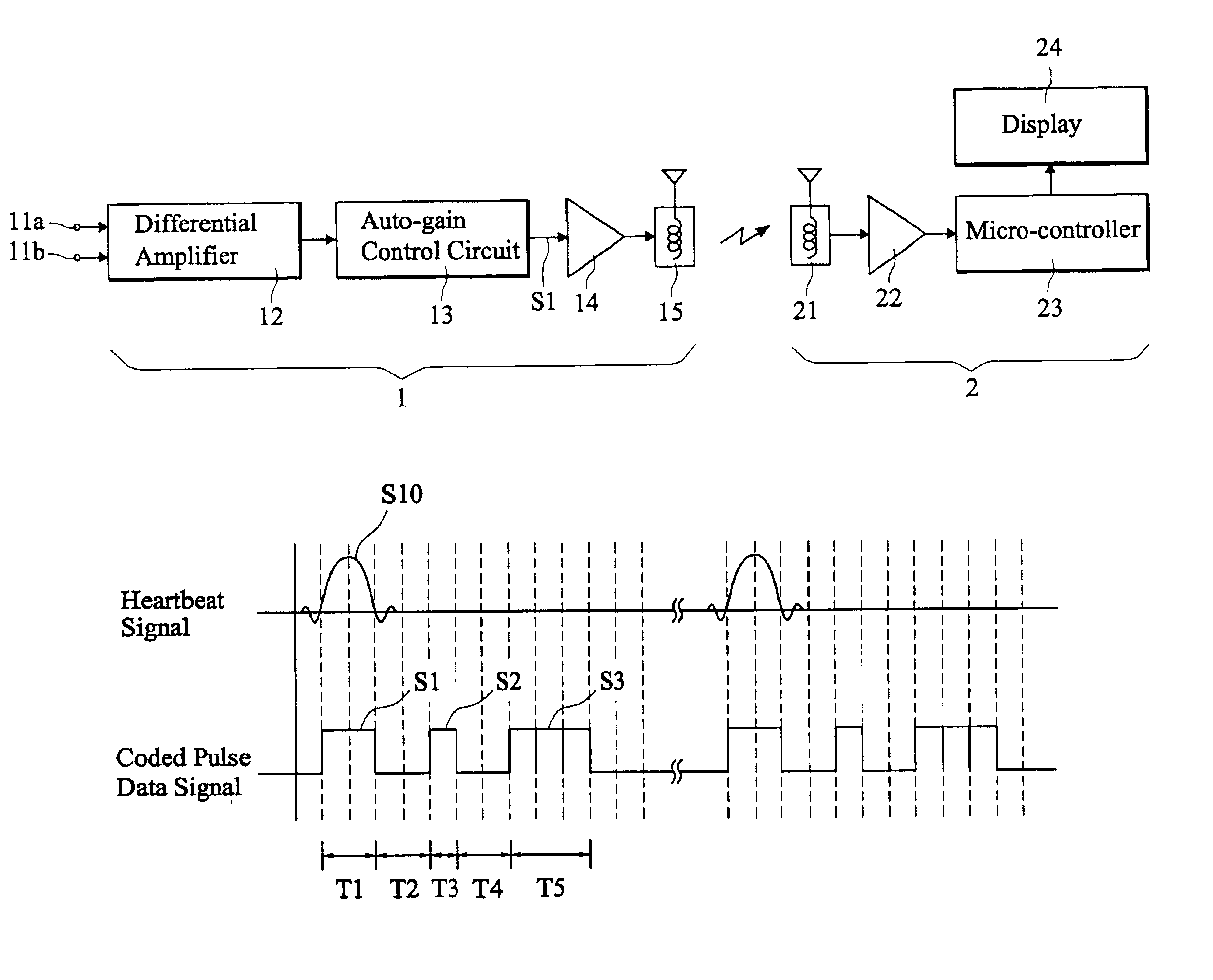
[0030]The check code pulse signal S3 is obtained by coding the pulse data signal S1 and the identification code pulse signal S2 in accordance with a predetermined coding process or coding protocol. The coding process may be, for example, an algorithm of addition (+), subtraction (−), multiplication (×), division (÷), or a ratio operation of the pulse data signal S1 and the identification code pulse signal S2. For instance, when the coding process for the check code pulse signal S3 is an algorithm of addition operation (+) in accordance with the present invention, then the time data for the coded pulse data signal of the heartbeat signal S10 are as follows:[0031]T1=10 ms[0032]T2=10 ms[0033]T3=5 ms[0034]T4=10 ms[0035]T5=T1+T3=10 ms+5 ms=15 ms.

[0036]In this embodiment, the check code pulse signal S3 has a pulse width T5 of 15 ms. Thus, the signal transmitted by the transmitter 1 and received at the receiver 2 end would be as follows:[0037]T1=10 ms[0038]T2=10 ms[0039]T3=5 ms[0040]T4=10 ...

second embodiment

[0043]Alternatively, based on the algorithm of addition operation (+), the check code pulse signal S3 may be obtained by extendedly coding the pulse duration T1 of the pulse data signal S1, the time interval T2, the pulse duration T3 of the identification code pulse signal S2, and the time interval T4 in accordance with the present invention. With reference to FIG. 6, in this embodiment, the time data for the coded pulse data signal of the heartbeat signal S10 are as follows:[0044]T1=10 ms[0045]T2=10 ms[0046]T3=5 ms[0047]T4=10 ms[0048]T5=T1+T3=10 ms+5 ms=15 ms[0049]T6=T2+T4=10 ms+10 ms=20 ms

[0050]That is, the pulse data coding processes of this embodiment comprises steps of summing the first pulse duration T1 of the pulse data signal S1 and the second duration T3 of the identification code pulse signal S2 to obtain a high state pulse width T5 of the check code pulse signal S3, and summing the first time interval T2 and the second time interval T4 to obtain a low state pulse width T6...

third embodiment

[0058]Please refer to FIG. 7. When, for example, the coding process for the check code pulse signal S3 is an algorithm of subtraction operation (−) in accordance with the present invention, then the time data for the coded pulse data signal of the heartbeat signal S10 are as follows:[0059]T1=10 ms[0060]T2=15 ms[0061]T3=5 ms[0062]T4=10 ms[0063]T5=T1−T3=10 ms−5 ms=5 ms

[0064]In this embodiment, the check code pulse signal S3 has a pulse width T5 of 5 ms. Thus, the signal transmitted by the transmitter 1 and received at the receiver 2 end would be as follows:[0065]T1=10 ms[0066]T2=15 ms[0067]T3=5 ms[0068]T4=10 ms[0069]T5=5 ms

[0070]Similarly, the receiver 2, on receipt of the coded pulse data signal transmitted by the transmitter 1, would check the check code pulse signal S3 of the received signal according to the predetermined coding process to determine whether the received signal is a correct signal.


PUM


Abstract

A pulse data coding method for wireless signal transmitting and receiving devices includes the steps of using a transmitter to transmit a signal of pulse data to be transmitted, transmitting at least one identification code pulse signal after a predetermined time interval from the transmission of the pulse data signal, and transmitting a check code pulse signal after another predetermined time interval from the transmission of the identification code pulse signal. The check code pulse signal is obtained by coding the pulse data signal and the identification code pulse signal according to a predetermined coding process. When a corresponding receiver receives the signal from the transmitter, it determines a correctness of the received signal according to the predetermined coding process, which may be an algorithm of addition, subtraction, multiplication, division, and / or a ratio operation.

Description

BACKGROUND OF THE INVENTION[0001]1. Field of the Invention[0002]The present invention relates to a wireless signal transmitting and receiving technique, and more particularly to a pulse data coding method for wireless signal transmitting and receiving devices, with which a pulse data signal transmitted by a transmitting device is protected against interference by noise signals and can therefore be correctly received by a corresponding receiving device.[0003]2. Description of the Prior Art[0004]It is a common practice in many electronic apparatus to transmit a signal of the electronic apparatus to a nearby receiving device by means of wireless transmitting / receiving technique, so that the electronic apparatus is more practical for use without being limited by a signal wire or cable. For example, most of the currently very popular exercise apparatus include a sensor to detect the user's heart rate, so that a signal of the detected heartbeat rate is processed by a transmitter and wirel...

Claims


Application Information

Patent Timeline
IPC IPC(8): H04L25/49A61B5/00
CPCH04L25/4902A61B5/0002
Inventor CHEN, SHUI JUNG
Owner DIRECTION TECH
Why Eureka
Try Eureka