Apparatus and methods for stabilization and control of fiber devices and fiber devices including the same

a technology apparatus, applied in the field of photonic devices, can solve the problems of difficult control using external inputs, affecting the filtering properties of fiber bragg grating, and unable to adjust or stabilize device properties,

Inactive Publication Date: 2005-11-01
INTEL CORP
View PDF3 Cites 4 Cited by
  • Summary
  • Abstract
  • Description
  • Claims
  • Application Information

AI Technical Summary

Problems solved by technology

One of the limitations of in-fiber devices is that they are difficult to control using external inputs, to tune or to stabilize device properties, for example.
When a fiber Bragg grating is attached to a substrate, however, the filtering properties of the fiber Bragg grating may be affected by the physical characteristics of the substrate.
Morey is limited, however, in that it does not compensate for other environmental conditions to which embedded Bragg grating filters may be subjected.

Method used


Image

  • Apparatus and methods for stabilization and control of fiber devices and fiber devices including the same
  • Apparatus and methods for stabilization and control of fiber devices and fiber devices including the same
  • Apparatus and methods for stabilization and control of fiber devices and fiber devices including the same

Examples


Embodiment Construction

[0022]Embodiments of the present invention are directed to photonic devices. In the following description, numerous specific details, such as particular processes, materials, devices, and so forth, are presented to provide a thorough understanding of embodiments of the invention. One skilled in the relevant art will recognize, however, that the invention can be practiced without one or more of the specific details, or with other methods, components, etc. In other instances, well-known structures or operations are not shown or described in detail to avoid obscuring understanding of this description.

[0023]Some parts of this description will be presented using terms such as in-fiber device, strain, photonic device, piezoelectric, laminate, and so forth. These terms are commonly employed by those skilled in the art to convey the substance of their work to others skilled in the art.

[0024]Various operations will be described as multiple discrete blocks performed in turn in a manner that i...


PUM


Abstract

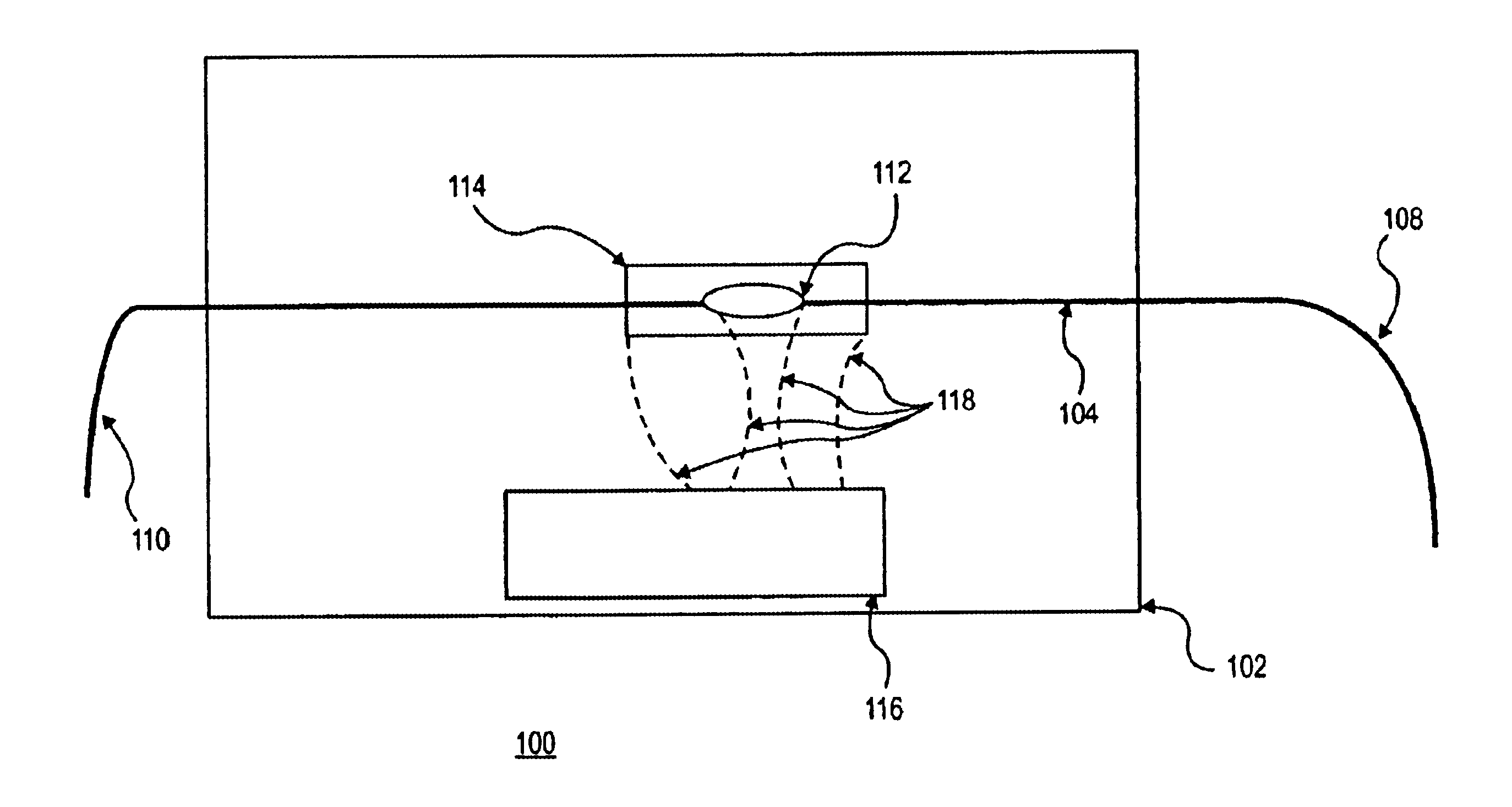
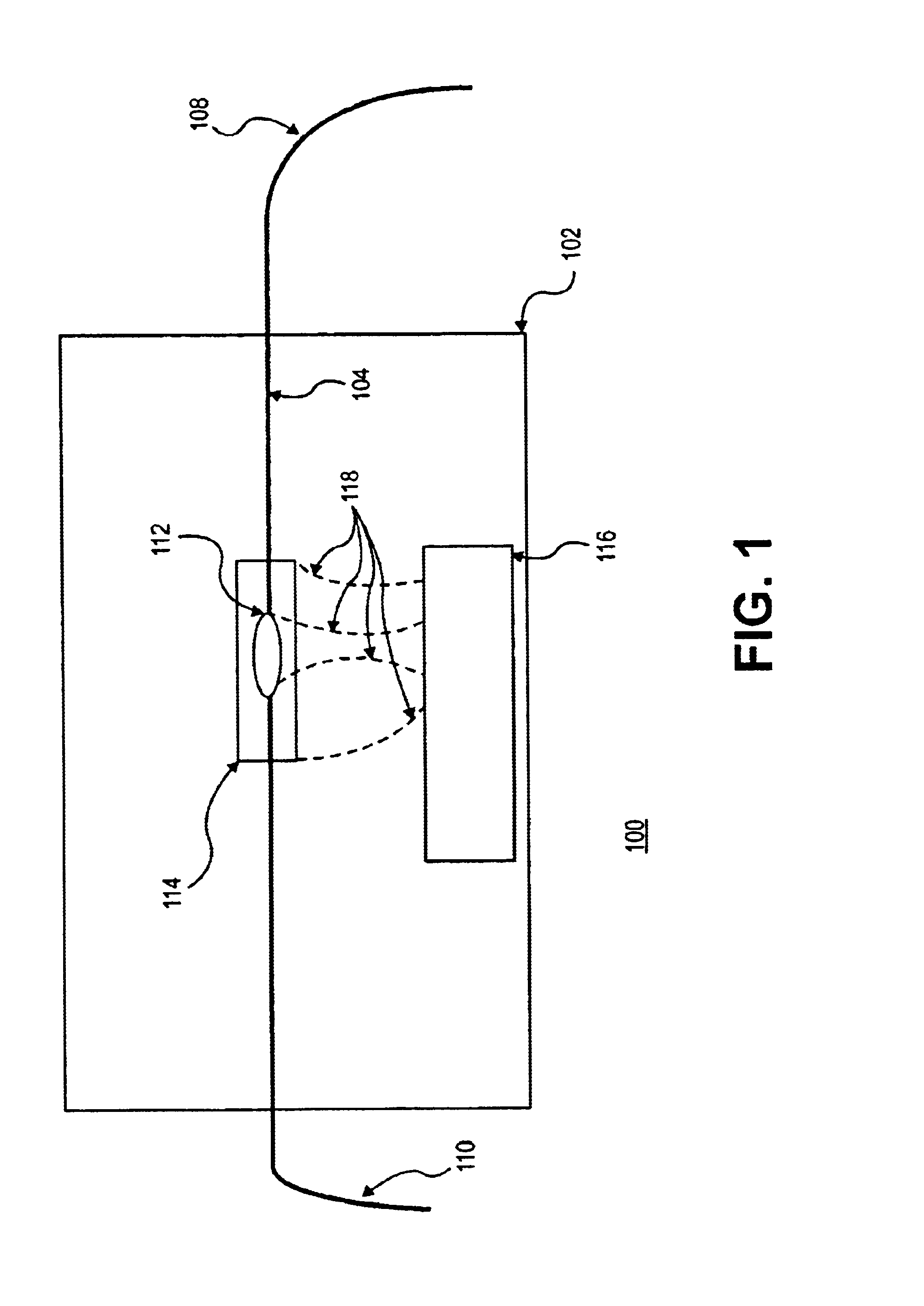
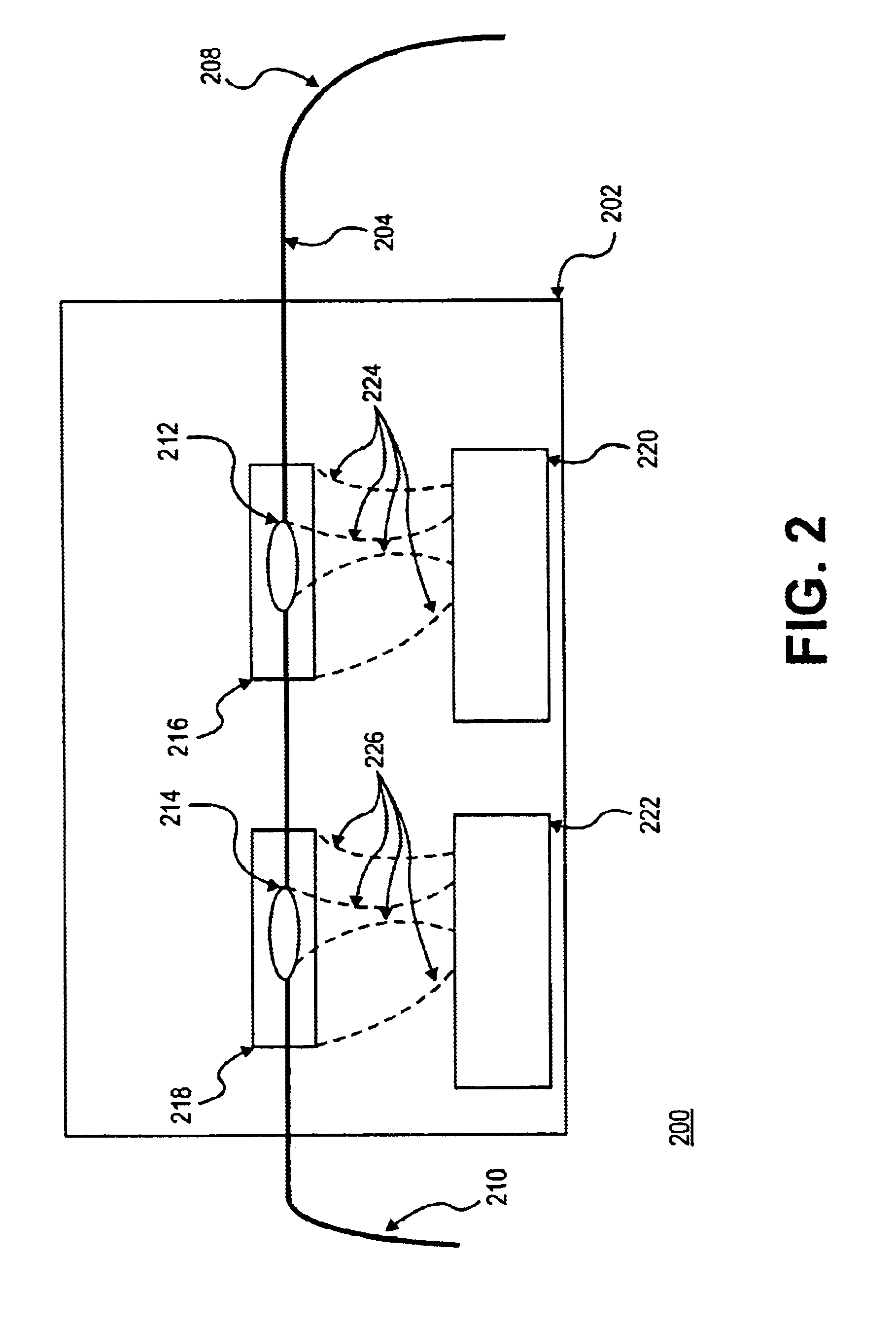
A mounting platform provides support and packaging for one or more fiber Bragg gratings and electronic circuitry (e.g., heaters, coolers, piezoelectric strain providers, temperature and strain sensors, feedback circuitry, control loops), which may be printed on or on the mounting platform, embedded in the mounting platform, or may be an “off-board” chip solution (e.g., the electronic circuitry may be attached to the mounting platform, but not formed on or defined on the mounting platform). The fiber Bragg gratings are held in close proximity to the electronic circuitry, which applies local and global temperature and / or strain variations to the fiber Bragg gratings to, for example, stabilize and / or tune spectral properties of the fiber Bragg gratings so that spatial variations in the fiber Bragg gratings that result from processing and manufacturing fluctuations and tolerances can be compensated for.

Description

[0001]This application claims benefit of provisional application No. 60 / 293,681 filed May 25, 2001.BACKGROUND[0002]1. Field[0003]Embodiments of the present invention relates to photonic devices and, more particularly, to stabilization and control of in-fiber photonic devices.[0004]2. Background Information[0005]An optical transmission system transmits information from one place to another by way of a carrier whose frequency is in the visible or near-infrared region of the electromagnetic spectrum. A carrier with such a high frequency is sometimes referred to as an optical signal, an optical carrier, or a lightwave signal.[0006]An optical transmission system typically includes several optical fibers. Each optical fiber includes several channels. A channel is a specified frequency band of an electromagnetic signal, and is sometimes referred to as a wavelength. One link of an optical transmission system typically has a transmitter, the optical fiber, and a receiver. The transmitter con...

Claims


Application Information

Patent Timeline
Patent Type & Authority Patents(United States)
IPC IPC(8): G01D5/353G01D5/26G02B6/02
CPCG02B6/0218G01D5/35316G02B6/02204G02B6/022
Inventor JOHNSON, ALAN E.GRUNNET-JEPSEN, ANDERSTSAI, TSUNG-EINSWEETSER, JOHN N.MILLER, MATTHEW
Owner INTEL CORP
Why Eureka
Try Eureka