
Bag manufacturing and packaging apparatus

Inactive Publication Date: 2005-11-08
ISHIDA CO LTD
View PDF2 Cites 6 Cited by
  • Summary
  • Abstract
  • Description
  • Claims
  • Application Information

AI Technical Summary

Benefits of technology

[0012]A purpose of the present invention is to provide a bag manufacturing and packaging apparatus that can smoothly feed a strip even when the strip to which bags are mounted lacks rigidity, automatically set the strip up to the mounting unit, and form appropriate slits in the strip.

Problems solved by technology

Nevertheless, if the strip S is formed from a material such as a thin resin that lacks rigidity, then the strip S will unfavorably sag downward between the feed roller unit and the strip mounting unit 30, and may not feed smoothly.
Accordingly, problems such as jamming of the strip S in the guide unit 49 (discussed later) and the like may arise, and unevenness in the mounting gap of the bags B on the strip S may result.
However, since the strip S is merely held by the feed roller unit, tension cannot be applied to the strip S when forming a slit.
Furthermore, in the strip mounting unit 30, because bags B are pressed (thermally welded) to the strip S by a pressing body 33c on a heater 33a, the strip S is held by the feed roller unit and the pressing body 33c, such that tension can be applied to the strip S. However, the pressing time is set extremely short so that the heat does not burn through the strip S. Accordingly, it is difficult to adjust the timing at which the cutter 45 should be operated, because there is limited timing for the operation of the cutter 45.
Nevertheless, if the strip S is formed from a thin resin that lacks rigidity, and if slits are formed in a state wherein tension is not applied to the strip S, then slits cannot be formed by just sliding the strip S over the cutter.
Furthermore, because the guide unit merely planarly guides the strip S only on its upper and lower surfaces, the strip S may drift in the transverse direction in the guide unit, and may not be fed smoothly.
As a result, the strip S may get caught in and jammed by the guide unit.
As a result, slits may not be accurately formed in the strip S, and the strip S may develop wrinkles, degrading its appearance.
Furthermore, when initially setting the strip S or if, instead of forming slits as described above, the strip S is completely cut, then it will be necessary to thread the strip S by hand from the feed roller unit up to the strip mounting unit 30, making it unamenable to automation.

Method used


Image

  • Bag manufacturing and packaging apparatus
  • Bag manufacturing and packaging apparatus
  • Bag manufacturing and packaging apparatus

Examples


Embodiment Construction

[0044]Selected embodiments of the present invention will now be explained with reference to the drawings. It will be apparent to those skilled in the art from this disclosure that the following description of the embodiments of the present invention is provided for illustration only, and not for the purpose of limiting the invention as defined by the appended claims and their equivalents.

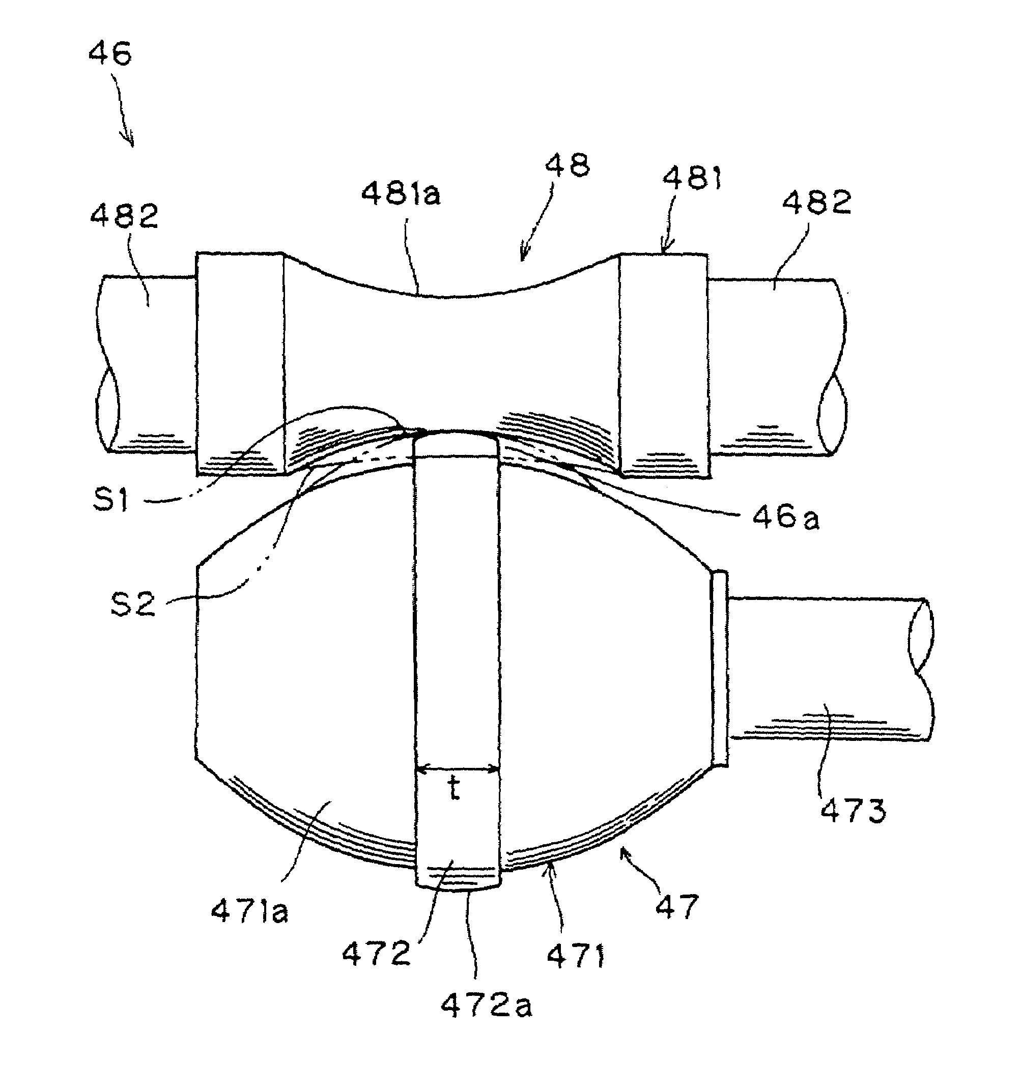
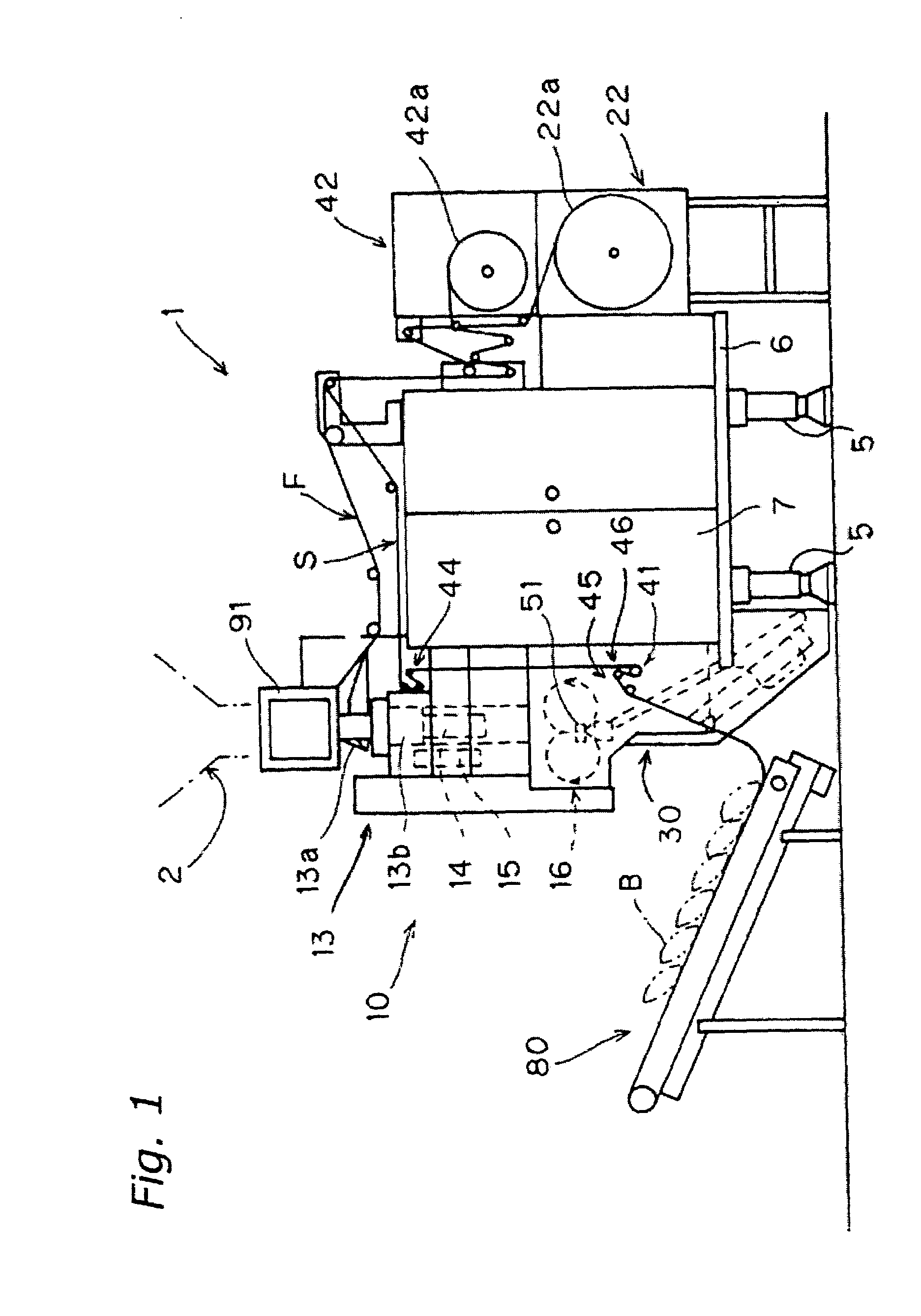
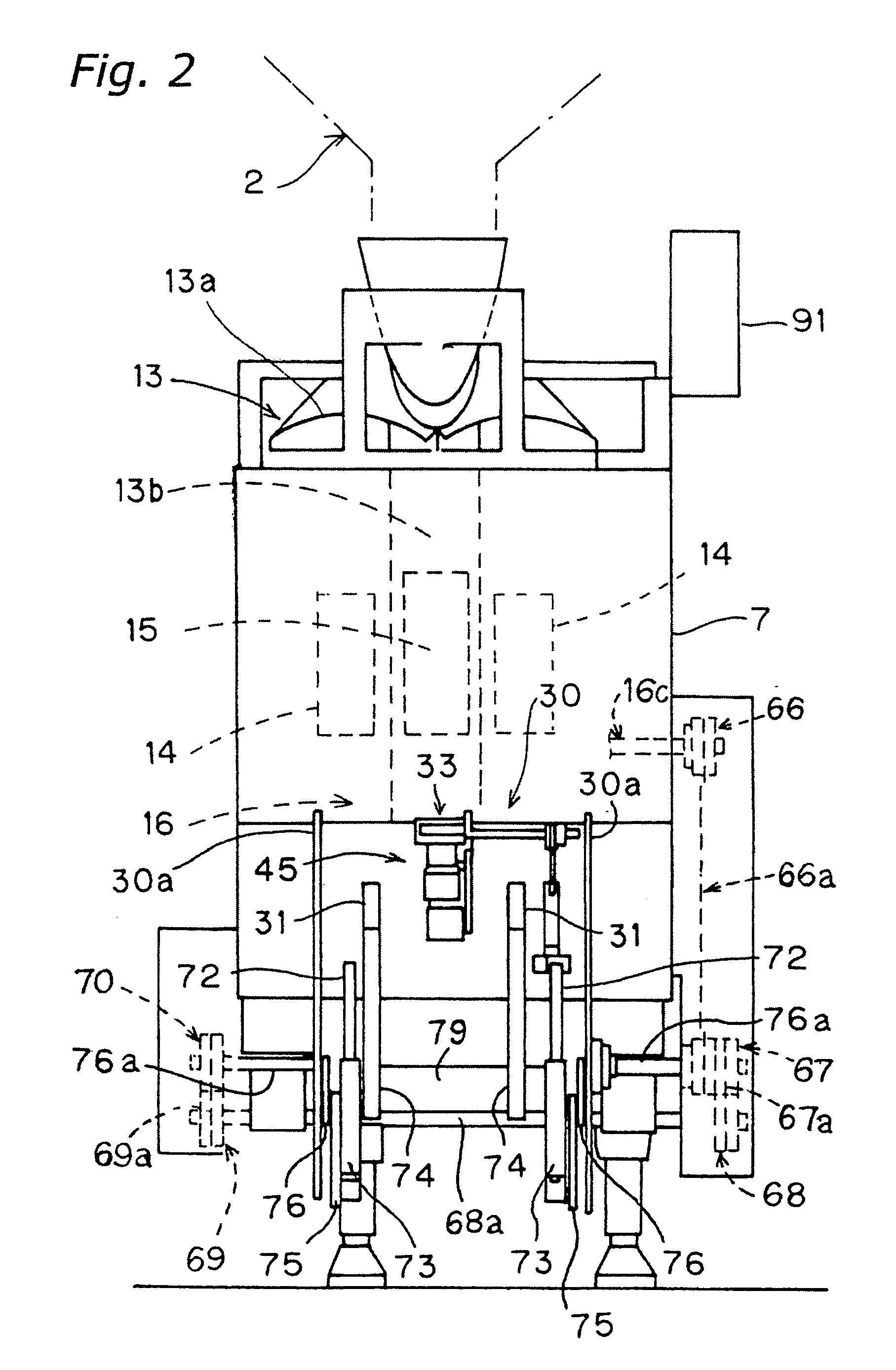
[0045]The following explains embodiments of the present invention, referring to the drawings. FIG. 1 is a side view of the entirety of a vertical bag manufacturing and packaging apparatus 1 according to one embodiment of the present invention, and FIG. 2 is its front view. The bag manufacturing and packaging apparatus 1 principally includes a bag manufacturing unit 10, a film roll holding unit 22, a strip mounting unit 30, a strip transport unit 41, a strip roll holding unit 42, a bend-imparting unit 45, a transport conveyor 80, and a control unit 90. The portion of the bag manufacturing and packagi...


PUM

PropertyMeasurementUnit
Transport propertiesaaaaaaaaaa
Stiffnessaaaaaaaaaa

Abstract

A bag manufacturing and packaging apparatus includes a bag manufacturing unit that tubularly forms a strip film and manufactures a bag filled with articles; a feed roller unit that feeds a strip, to which the bag manufactured by the bag manufacturing unit is mounted; and a mounting unit that mounts the bag to the strip fed by the feed roller unit. The strip is rectilinearly maintained between the feed roller unit and the mounting unit by imparting a bend on the strip in the transverse cross section that intersects a transport pathway of the strip. The object of the present invention is to provide a bag manufacturing and packaging apparatus that, even if the strip to which bags are mounted lacks rigidity, can smoothly feed the strip, automatically thread the strip to the mounting unit, and form appropriate slits in the strip.

Description

BACKGROUND OF THE INVENTION[0001]1. Field of the Invention[0002]This invention generally relates to a bag manufacturing and packaging apparatus. More specifically, the present invention relates to a bag manufacturing and packaging apparatus that forms a strip film into a tubular shape, manufactures bags filled with articles, and mounts those bags to a strip narrower than the bags.[0003]2. Background Information[0004]In one mode of displaying articles in a retail store, a plurality of bags in which articles like snacks and candies are filled and packaged, are attached to a strip for displaying the articles, leaving a small gap between each bag. This way, the bags are arranged vertically by hanging the end of the strip. A suspended bag can be removed from the strip by a customer without damaging the seal of the bag by pulling the bag downward and thereby detaching the bag. To manufacture such an apparatus, it has been suggested to impart to a bag manufacturing and packaging apparatus ...

Claims


Application Information

Patent Timeline
IPC IPC(8): B65B15/04B65B15/00B65B9/10B65B9/20
CPCB65B9/2021B65B9/207B65B15/04B65B51/306B65B61/28B65B61/16
Inventor YAMAMOTO, AKIRAIWASAKI, YOSHIONAKAGAWA, YUKIOYAMAGUCHI, YASUSHIITO, TATSUO
Owner ISHIDA CO LTD
Learn More